Kia Cadenza YG: Engine Control System / Accelerator Position Sensor (APS) Schematic Diagrams
Kia Cadenza YG 2016-2021 Service Manual / Engine Control / Fuel System / Engine Control System / Accelerator Position Sensor (APS) Schematic Diagrams
| Circuit Diagram |
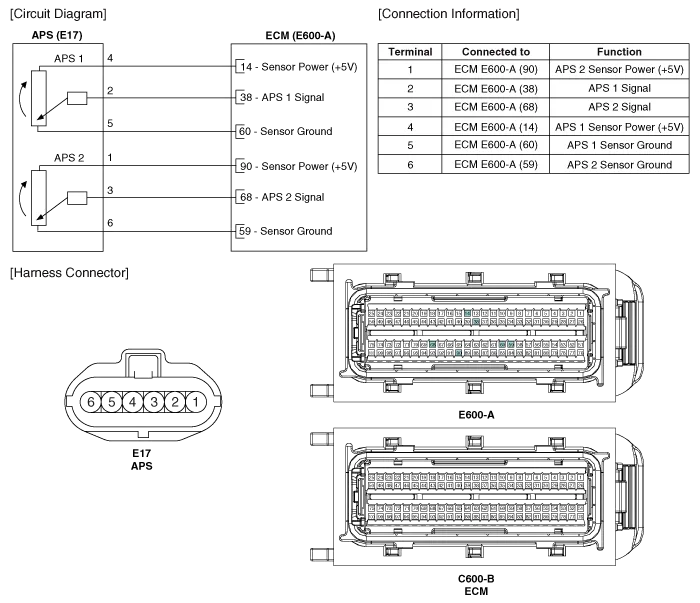
Specification AcceleratorPositionOutput Voltage (V)APS1APS2C.T0.7 ~ 0.80.29 ~ 0.46W.O.T3.85 ~ 4.351.93 ~ 2.18
Inspection 1. Connect the GDS on the Data Link Connector (DLC). 2. Turn the ignition switch ON. 3. Measure the output voltage of the APS 1 and 2 at C.
Other information:
Kia Cadenza YG 2016-2021 Service Manual: Repair procedures
Refrigerant System Service Basics Refrigerant Recovery Use only service equipment that is U.L-listed and is certified to meet the requirements of SAE J2210 to remove HFC-134a(R-134a) from the air conditioning system. – Air conditioning refrigerant or lubricant vapor can irritate your eyes, nose, or th
Kia Cadenza YG 2016-2021 Service Manual: Intake Actuator Description and Operation
D
Categories
- Manuals Home
- Kia Cadenza Owners Manual
- Kia Cadenza Service Manual
- Suspension System
- Timing Chain Repair procedures
- Battery Troubleshooting
- New on site
- Most important about car

Copyright © 2026 www.kcadenzavg.com - 0.0241