Kia Cadenza YG: Engine Control System / Accelerator Position Sensor (APS) Repair procedures
| Inspection |
| 1. |
Connect the GDS on the Data Link Connector (DLC). |
| 2. |
Turn the ignition switch ON. |
| 3. |
Measure the output voltage of the APS 1 and 2 at C.T and W.O.T.
|
| Removal |
| 1. |
Turn the ignition switch OFF and disconnect the negative (-) battery cable. |
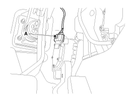
| 2. |
Disconnect the accelerator position sensor connector (A).
|
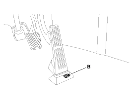
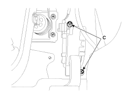
| 3. |
Remove the installation bolt (B) and nuts (C), and the remove the accelerator pedal medule.
|
| Installation |
| 1. |
Install in the reverse order of removal.
|
Circuit Diagram
Description Fuel Tank Pressure Sensor (FTPS) is a component of the evaporative emission control system and is installed on the fuel tank, the fuel pump, or the canister.
Other information:
Kia Cadenza YG 2016-2021 Service Manual: Parking Assist Sensor Repair procedures
Removal 1. Disconnect the negative (-) battery terminal. 2. Remove the rear bumper cover. (Refer to Body - "Rear Bumper Cover") 3. Disconnect the connector (A) from the parking assist sensor. 4. Pull out the sensor (A) by opening the sensor holder (B) out.
Kia Cadenza YG 2016-2021 Service Manual: Temperature Control Actuator Repair procedures
Inspection 1. Ignition "OFF" 2. Disconnect the connector of temperature control actuator. 3. Verify that the temperature control actuator operates to the hot position when connecting 12V to the terminal 3 and grounding terminal 7. Verify that the temperature control actuator operates to the cool position when connecting in the rev
Categories
- Manuals Home
- Kia Cadenza Owners Manual
- Kia Cadenza Service Manual
- Alternator Schematic Diagrams
- Engine Mechanical System
- General Information
- New on site
- Most important about car
