Kia Cadenza YG: Charging System / Alternator Repair procedures
| Removal |
| 1. |
Disconnect the battery negative terminal. |
| 2. |
Remove the engine cover. |
| 3. |
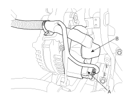
Disconnect the alternator connector (A) and cable (B) from the ''B'' terminal.
|
| 4. |
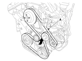
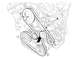
To release the tension, turn the drive belt tensioner counterclockwise then remove the drive belt (A).
|
| 5. |
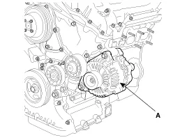
Remove the alternator (A).
|
| Installation |
| 1. |
Install in the reverse order of removal.
|
| 2. |
Adjust the alternator belt tension after installation.
|

Circuit Diagram • COM signal - When controlling the voltage generated, the ECM sends the target voltage data to the alternator via a PWM signal.
Description 1. The CMF(Closed Maintenance Free) battery is, as the name implies, totally maintenance free and has no removable battery cell caps.
Other information:
Kia Cadenza YG 2016-2021 Service Manual: Blind Spot Detection Radar Calibration Description and Operation
Description To sense the cars exactly in the next lane with the radar, the direction of the sensor and the direction of the vehicle have to align. This is BSD unit alignment. If this alignment is not performed as below illustration, the degradation of detection performance and the cause of false alarms.
Kia Cadenza YG 2016-2021 Service Manual: Troubleshooting
Troubleshooting Examples of False-Alarm Occurrence from system characteristics (It’s not a problem) – Characteristics of EM Wave : EM Waves are reflected against all material and especially metal very well. Reflections of EM Waves are varies with the shape of object.
Categories
- Manuals Home
- Kia Cadenza Owners Manual
- Kia Cadenza Service Manual
- Specifications
- Automatic Transaxle System
- Engine Control / Fuel System
- New on site
- Most important about car
