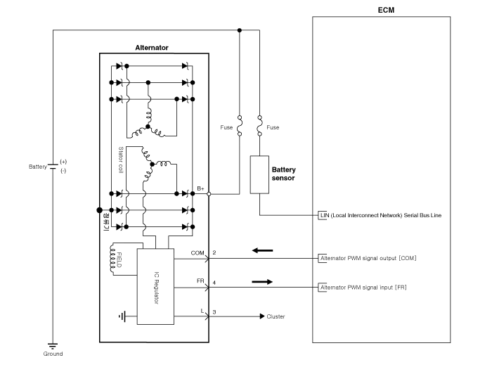
Kia Cadenza YG: Charging System / Alternator Schematic Diagrams
| Circuit Diagram |
|

Specification ItemSpecificationRated voltage13.5V , 150ASpeed in use1,500 ~ 18,000rpmVoltage regulatorIC Regulator built in typeDefault regulated voltage (V) [COM terminal]14.
Removal 1. Disconnect the battery negative terminal. 2. Remove the engine cover. 3. Disconnect the alternator connector (A) and cable (B) from the ''B'' terminal.
Other information:
Kia Cadenza YG 2016-2021 Service Manual: Immobilizer Control Unit Repair procedures
Removal 1. Disconnect the negative (-) battery terminal. 2. Remove the crash pad lower panel. (Refer to Body - "Crash Pad") 3. Disconnect the 5P connector of the SMARTRA unit and then remove the SMARTRA unit (A) after loosening the bolt. Installation 1.
Kia Cadenza YG 2016-2021 Service Manual: Lane Departure Warning System (LDWS) Unit Repair procedures
Removal 1. Disconnect the negative (-) battery terminal. 2. Remove the LDWS unit cover (A). 3. Remove the LDWS unit connector (A). 4. Remove the LDWS unit after widening the mounting clips. Installation 1. Install the LDWS unit. 2.
Categories
- Manuals Home
- Kia Cadenza Owners Manual
- Kia Cadenza Service Manual
- Timing Chain Repair procedures
- Body (Interior and Exterior)
- Emission Control System
- New on site
- Most important about car
