
Kia Cadenza YG: Air Conditioning System / Auto defoging sensor Repair procedures
Kia Cadenza YG 2016-2021 Service Manual / Heating,Ventilation, Air Conditioning / Air Conditioning System / Auto defoging sensor Repair procedures
| Inspection |
| 1. |
Press the OFF switch more then 4 times within 2 seconds while pressing the MODE switch.
* Diagnostic procedure refer to DTC code. |
| Replacement |
| 1. |
Disconnect the negative (-) battery terminal. |
| 2. |
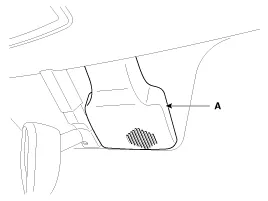
Remove the auto defogging sensor cover(A).
|
| 3. |
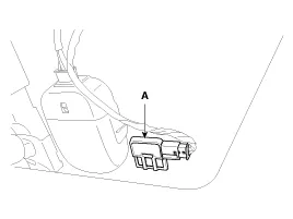
Disconnect the connector and then remove the auto defogging sensor(A).
|
| 4. |
Installation is the reverse order of removal. |
Description Achieve exclusion function on croaker before fogging occurrence. Senses vehicles rational moisture and proves watch security and amenities.
Component location
Other information:
Kia Cadenza YG 2016-2021 Service Manual: Description and Operation
Description Back view camera will activate when the backup light is ON with the ignition switch ON and the shift lever in the R position. This system is a supplemental system that shows behind the vehicle through the ECM (Reverse Display Room Mirror) mirror or AVN head unit while backing-up.
Kia Cadenza YG 2016-2021 Service Manual: Heater Unit Components and Components Location
Component Location Components 1. Heater Case (LH)2. Separator3. Evaporator Core4. Shower Duct (LH)5. Heater Core Cover6. Heater Core7. Mode Actuator8. Mode Cam9. Temp Actuator (Drive)10. Vent Door Arm11. Floor Door Arm 1. Heater Case (RH)2.
Categories
- Manuals Home
- Kia Cadenza Owners Manual
- Kia Cadenza Service Manual
- General Information
- Engine Mechanical System
- Timing Chain Repair procedures
- New on site
- Most important about car

Copyright © 2026 www.kcadenzavg.com - 0.0268