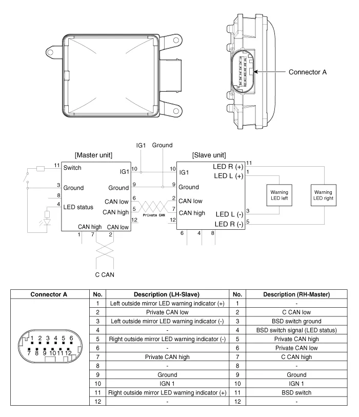
Kia Cadenza YG: Blind Spot Detection System / Blind Spot Detection Unit Schematic Diagrams
| Circuit Diagram |
Diagnosis With GDS 1. BSD system defects can be quickly diagnosed with the GDS. GDS operates actuator quickly to monitor, input/output value and self diagnosis.
Removal 1. Disconnect the negative (-) battery terminal. 2. Remove the rear bumper. (Refer to Body - "Rear Bumper") 3. Remove the BSD unit (A) after loosening the mounting screws.
Other information:
Kia Cadenza YG 2016-2021 Service Manual: Description and Operation
Description System Overview The System offers the following features: – Human / machine interface through a 1-stage button, for terminal switching and engine start. – Control of external relays for ACC / IGN1 / IGN2 terminal switching and STARTER, without use of mechanical ignition switch.
Kia Cadenza YG 2016-2021 Service Manual: Compressor Oil Repair procedures
Oil Specification 1. The HFC-134a system requires synthetic (PAG) compressor oil whereas the R-12 system requires mineral compressor oil. The two oils must never be mixed. 2. Compressor (PAG) oil varies according to compressor model. Be sure to use oil specified for the model of compressor.
Categories
- Manuals Home
- Kia Cadenza Owners Manual
- Kia Cadenza Service Manual
- Automatic Transaxle System
- Emission Control System
- Body (Interior and Exterior)
- New on site
- Most important about car
