Kia Cadenza YG: BCM (Body Control Module) / Body Control Module (BCM) Repair procedures
Kia Cadenza YG 2016-2021 Service Manual / Body Electrical System / BCM (Body Control Module) / Body Control Module (BCM) Repair procedures
| Removal |
| 1. |
Disconnect the negative (-) battery terminal. |
| 2. |
Remove the crash pad lower panel (A).
|

| 3. |
Remove the Reinforcing panel after loosening the mounting bolt and nut.
(Refer to Body - " Crash Pad") |
| 4. |
Disconnect the IPM connectors, loosening the nuts(2EA) and bolt (1EA).
|
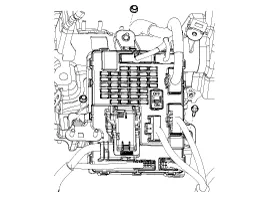
| 5. |
Disconnect the rear connector, and then remove the IPM. |
| Installation |
| 1. |
Install the IPM. |
| 2. |
Install the reinforcing panel. |
| 3. |
Install the crash pad lower panel. |
| 4. |
Disconnect the negative (-) battery terminal. |
| IPM Diagnosis With GDS |
| 1. |
It will be able to diagnose defects of IPM with GDS quickly.
GDS can operates actuator forcefully, input/output value monitoring and
self diagnosis. |
| 2. |
Select model and "IPM". |
| 3. |
Select the module to check. |
| 4. |
Select "Input/output monitoring", if you will check current
data of body network system. It provides input/output status of each
module.
|

| 5. |
If you will check each module data operation forcefully, select "Actuation test".
|

| 6. |
To check the DTC of the each module, select "DIAGNOSTIC TROUBLE CODES".
|

| 7. |
If you want to change user option, select “user option”.
|

IPM Overview The Body Control Module (IPM-Intelligent integrated Platform Module) supplies vehicle occupants with visual and audible information and controls various vehicle functions.
Other information:
Kia Cadenza YG 2016-2021 Service Manual: Auto Head lamp leveling Unit Repair procedures
Removal Height Sensor 1. Remove the height sensor connector (A). 2. Loosen the mounting bolts(Body: 2EA, chassis: 1EA) from height sensor bracket. Tightening torque : 3 ~ 5N.m (30 ~ 50kgf.m, 2.21 ~ 3.68lb-ft) 3. Remove the height sensor.
Kia Cadenza YG 2016-2021 Service Manual: Blind Spot Detection Unit Repair procedures
Removal 1. Disconnect the negative (-) battery terminal. 2. Remove the rear bumper. (Refer to Body - "Rear Bumper") 3. Remove the BSD unit (A) after loosening the mounting screws. Take care not to separate the bracket from rear bumper when removing the BSD sensor.
Categories
- Manuals Home
- Kia Cadenza Owners Manual
- Kia Cadenza Service Manual
- Engine And Transmission Assembly
- Transaxle Control Module (TCM) Repair procedures
- Body (Interior and Exterior)
- New on site
- Most important about car

Copyright © 2026 www.kcadenzavg.com - 0.0222