Kia Cadenza YG: Fuel Delivery System / Components and Components Location
Kia Cadenza YG 2016-2021 Service Manual / Engine Control / Fuel System / Fuel Delivery System / Components and Components Location
| Components Location |
| [Fuel Tank] |
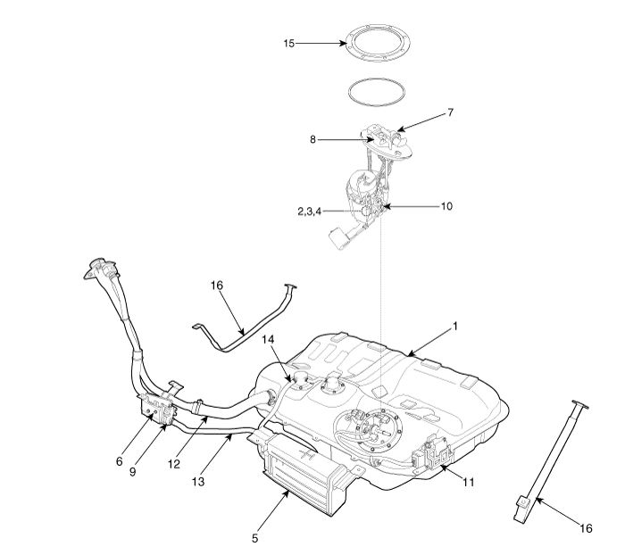
| 1. Fuel Tank 2. Fuel Pump 3. Fuel Filter 4. Fuel Pressure Regulator 5. Canister 6. Fuel Tank Air Filter 7. Fuel Pressure Sensor (FPS) 8. Fuel Tank Pressure Sensor (FTPS) | 9. Canister Close Valve (CCV) 10. Fuel Level Sender (FLS) 11. Fuel Pump Control Module (FPCM) 12. Fuel Filler Hose 13. Ventilation Hose 14. Vapor Tube 15. Fuel Pump Plate Cover 16. Fuel Tank Band |
| [Fuel Pump Assembly] |

| 1. Fuel Pump Plate Cover 2. Head Assembly 3. Fuel Filter 4. Fuel Pressure Regulator | 5. Fuel Pump Motor 6. Pre-filter 7. Reservoir-cup 8. Fuel Sender |
| [High Pressure Fuel Line] |

| 1. High Pressure Fuel Pump 2. High Pressure Fuel Pipe | 3. Delivery Pipe 4. Injector |
In case of removing the high pressure fuel pump, high
pressure fuel pipe, delivery pipe, and injector, there may be injury
caused by leakage of the high pressure fuel. So don’t do any repair
work right after engine stops. |

Fuel Pressure Test (Low pressure system) 1. Release the residual pressure in fuel line. (Refer to the Fuel Delivery System - Repair Procedures - "Release Residual Pressure in Fuel Line").
Other information:
Kia Cadenza YG 2016-2021 Service Manual: Auto defoging sensor Repair procedures
Inspection 1. Press the OFF switch more then 4 times within 2 seconds while pressing the MODE switch. DisplayFail description00Normal23Auto defog sensor OPEN24Auto defog sensor SHORT43Defog door potentiometer OPEN/SHORT44Defog door potentiometer * Diagnostic procedure refer to DTC code.
Kia Cadenza YG 2016-2021 Service Manual: Auto defoging actuator Repair procedures
Inspection 1. Ignition "OFF”. 2. Disconnect the connector of auto defog control actuator. 3. Verify that the auto defog control actuator operates to the defrost ON mode when connecting 12V to the terminal 3 and grounding terminal 7. 4.
Categories
- Manuals Home
- Kia Cadenza Owners Manual
- Kia Cadenza Service Manual
- Suspension System
- Body Electrical System
- Steering System
- New on site
- Most important about car

Copyright © 2026 www.kcadenzavg.com - 0.0216