Kia Cadenza YG: AVN System / Components and Components Location
| Components Location |
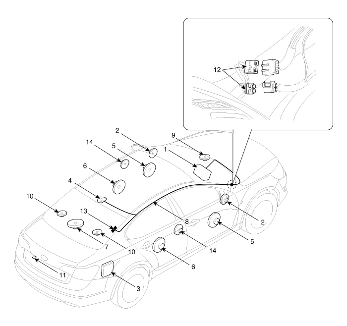
| 1. AVN (A/V & Navigation head unit) 2. Front tweeter speaker 3. External amplifier 4. Roof antenna 5. Front door speaker 6. Rear door speaker 7. Sub woofer speaker | 8. Antenna feeder cable 9. Front center speaker 10. Surround speaker 11. Back view camera 12. Feeder cable joint connector 13. Glass antenna (Radio) 14. Rear tweeter speaker |
Specifications AVN Head Unit ItemSpecificationPower sourceDC 14.4V (-) groundFrequency range / Channel spaceFM : 87.5 ~ 107.9 MHz / 200 KHzAM : 530 ~ 1710 KHz / 10 KHzTuning typePLL SYNTHESIZED TUNINGImpedance2 ohm x 4Antenna80 pF 75 OhmDark currentMax.
System Block Diagram
Other information:
Kia Cadenza YG 2016-2021 Service Manual: Blind Spot Detection Unit Repair procedures
Removal 1. Disconnect the negative (-) battery terminal. 2. Remove the rear bumper. (Refer to Body - "Rear Bumper") 3. Remove the BSD unit (A) after loosening the mounting screws. Take care not to separate the bracket from rear bumper when removing the BSD sensor.
Kia Cadenza YG 2016-2021 Service Manual: Power Mosfet Repair procedures
Inspection 1. Ignition "ON" 2. Manually operate the control switch and measure the voltage of blower motor. 3. Select the control switch to raise voltage until high speed. Specification FanMotor VoltageManualFirst speed3.8 ±0.5VSecond speed5.
Categories
- Manuals Home
- Kia Cadenza Owners Manual
- Kia Cadenza Service Manual
- Components and Components Location
- Steering System
- Alternator Schematic Diagrams
- New on site
- Most important about car
