Kia Cadenza YG: Engine Control System / CVVT Oil Control Valve (OCV) Repair procedures
| Inspection |
| 1. |
Turn the ignition switch OFF. |
| 2. |
Disconnect the OCV connector. |
| 3. |
Measure resistance between the OCV terminals 1 and 2. |
| 4. |
Check that the resistance is within the specification.
|
| Removal |
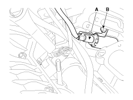
| [CVVT Oil Control Valve (Intake)] |
| 1. |
Turn the ignition switch OFF and disconnect the battery negative (-) cable. |
| 2. |
Remove the intake manifold.
(Refer to Engine Mechanical System - “Intake Manifold”) |
| 3. |
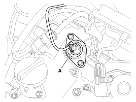
Disconnect the CVVT oil control valve connector (A). |
| 4. |
Remove the installation bolt (B), and then remove the valve from the engine.
[Bank 1]
[Bank 2]
|
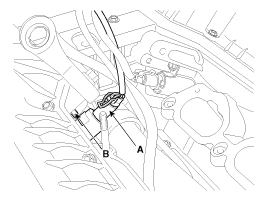
| [CVVT Oil Control Valve (Bank1/Exhaust)] |
| 1. |
Turn the ignition switch OFF and disconnect the battery negative (-) cable. |
| 2. |
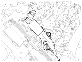
Disconnect the CVVT oil control valve connector (A).
|
| 3. |
Remove the surge tank.
(Refer to Engine Mechanical System - "Surge Tank") |
| 4. |
Remove the cylinder head cover.
(Refer to Engine Mechanical System - “Cylinder Head Cover”) |
| 5. |
Remove the installation bolt (A), and then remove the valve from the engine.
|
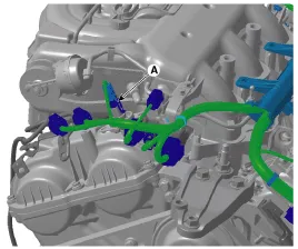
| [CVVT Oil Control Valve (Bank2/Exhaust)] |
| 1. |
Turn the ignition switch OFF and disconnect the battery negative (-) cable. |
| 2. |
Disconnect the CVVT oil control valve connector (A).
|
| 3. |
Remove the cylinder head cover.
(Refer to Engine Mechanical System - “Cylinder Head Cover”) |
| 4. |
Remove the installation bolt (A), and then remove the valve from the engine.
|
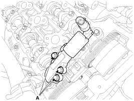
| Inatallation |
|

|
|
| Items | Component Side | Harness Side |
| Bank 1 (RH) | Grey | |
| Bank 2 (LH) | Black | |
| 1. |
Install in the reverse order of removal.
|
Circuit Diagram
Description Variable Intake manifold Solenoid (VIS) valves are installed on the intake manifold (VIS Valve 1) and the surge tank (VIS Valve 2). These VIS valve 1 and 2 control vacuum modulators which activate valves in the intake manifold and the surge tank.
Other information:
Kia Cadenza YG 2016-2021 Service Manual: Immobilizer Control Unit Repair procedures
Removal 1. Disconnect the negative (-) battery terminal. 2. Remove the crash pad lower panel. (Refer to Body - "Crash Pad") 3. Disconnect the 5P connector of the SMARTRA unit and then remove the SMARTRA unit (A) after loosening the bolt. Installation 1.
Kia Cadenza YG 2016-2021 Service Manual: A/C Pressure Transducer Repair procedures
Inspection 1. Measure the pressure of high pressure line by measuring voltage output between NO.1 and NO.2 terminals. 2. Inspect the voltage value whether it is sufficient to be regular value or not. Voltage = 0.00878835 * Pressure + 0.37081095 [PSIA] 3.
Categories
- Manuals Home
- Kia Cadenza Owners Manual
- Kia Cadenza Service Manual
- Schematic Diagrams
- Suspension System
- Fuel Delivery System
- New on site
- Most important about car
