Kia Cadenza YG: Cylinder Block / Drive Plate Repair procedures
Kia Cadenza YG 2016-2021 Service Manual / Engine Mechanical System / Cylinder Block / Drive Plate Repair procedures
| Removal and Installation |
| 1. |
Remove the automatic transaxle .
(Refer to Automatic Transaxle System - "Automatic Transaxle") |
| 2. |
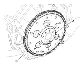
Remove the adapter plate (A) and the drive plate (B).
|
| 3. |
Install in the reverse order of removal. |
Components 1. Drive plate2. Adapter plate
Components 1. Rear oil seal2. Oil seal case
Other information:
Kia Cadenza YG 2016-2021 Service Manual: Description and Operation
Description Adaptive Front-lighting System (AFLS) AFLS(Adaptive Front-lighting System)is a headlamp orientation control system that takes into account both steering angle and vehicle speed to orient the headlamps to an angle that provides better nighttime visibility.
Kia Cadenza YG 2016-2021 Service Manual: Compressor Repair procedures
Removal 1. If the compressor is marginally operable, run the engine at idle speed, and let the air conditioning work for a few minutes, then shut the engine off. 2. Disconnect the negative cable from the battery. 3. Recover the refrigerant with a recovery/charging station.
Categories
- Manuals Home
- Kia Cadenza Owners Manual
- Kia Cadenza Service Manual
- Engine Control / Fuel System
- Restraint
- Suspension System
- New on site
- Most important about car

Copyright © 2026 www.kcadenzavg.com - 0.0265