Kia Cadenza YG: Parking Brake System / Electric Parking Brake (EPB) Repair procedures
| Removal |
| 1. |
Turn ignition OFF and disconnect the negative (-) battery cable. |
| 2. |
Remove the crash pad lower panel and reinforcing panel (A).
(Refer to the Body group - “Crash pad”) |
| 3. |
EPB control unit mounting nuts (B) and then remove EPB control unit.
|
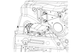
| 4. |
Disconnect the EPB control unit connector (A). |
| Installation |
| 1. |
Installation is the reverse of removal. |
| 2. |
Check that the brake operates normally by pushing the EPB switch more than 3 times after installing the EPB module.
|
EPB Circuit Diagram EPB connector input/output Pin No.Description1CAN_High2CAN_Low18IGN (+)19EPB Switch Signal 121EPB Switch Signal 327EPB Switch Signal 229EPB Switch Signal 433Rear Left Motor (-)34Ground35Ground36Rear Right Motor (-)37Rear Right Motor (+)38Rear Left Motor (+)39Battery (Rear Right Motor)40Battery (Rear Left Motor)
Removal 1. Turn ignition OFF and disconnect the negative (-) battery cable. 2. Remove the floor console upper cover. (Refer to Body group - "Console") 3.
Other information:
Kia Cadenza YG 2016-2021 Service Manual: Repair procedures
Inspection Tolerance Calibration Tolerance calibration compensates for the error margins of surround view video that occur due to the installation tolerance when the four cameras that comprise the SVM system are installed. You must carry out tolerance calibration if you do any of the following.
Kia Cadenza YG 2016-2021 Service Manual: Blind Spot Detection Unit Repair procedures
Removal 1. Disconnect the negative (-) battery terminal. 2. Remove the rear bumper. (Refer to Body - "Rear Bumper") 3. Remove the BSD unit (A) after loosening the mounting screws. Take care not to separate the bracket from rear bumper when removing the BSD sensor.
Categories
- Manuals Home
- Kia Cadenza Owners Manual
- Kia Cadenza Service Manual
- Rail Pressure Sensor (RPS) Schematic Diagrams
- Emission Control System
- Suspension System
- New on site
- Most important about car
