Kia Cadenza YG: Parking Brake System / Electric Parking Brake (EPB) Schematic Diagrams
| EPB Circuit Diagram |
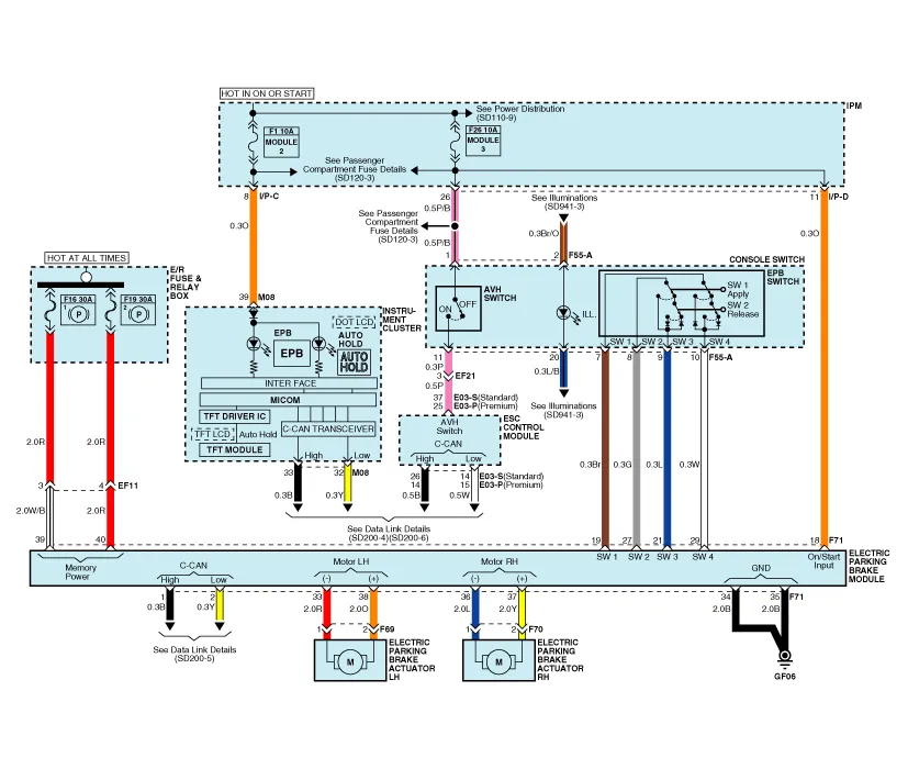
| EPB connector input/output |
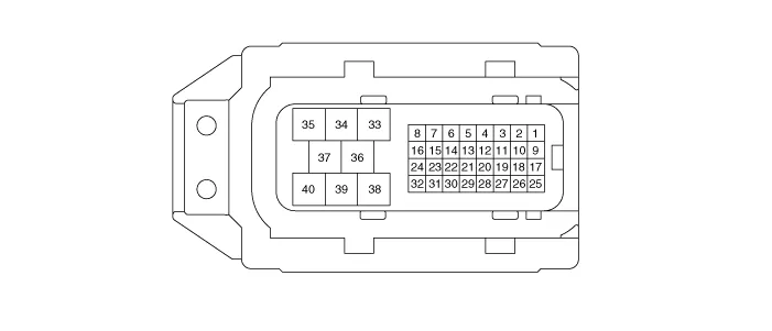
| Pin No. | Description |
| 1 | CAN_High |
| 2 | CAN_Low |
| 18 | IGN (+) |
| 19 | EPB Switch Signal 1 |
| 21 | EPB Switch Signal 3 |
| 27 | EPB Switch Signal 2 |
| 29 | EPB Switch Signal 4 |
| 33 | Rear Left Motor (-) |
| 34 | Ground |
| 35 | Ground |
| 36 | Rear Right Motor (-) |
| 37 | Rear Right Motor (+) |
| 38 | Rear Left Motor (+) |
| 39 | Battery (Rear Right Motor) |
| 40 | Battery (Rear Left Motor) |
Description The EPB is an electronic parking brake. The EPB is different from existing parking systems which operated with the brake pedal or the lever type.
Removal 1. Turn ignition OFF and disconnect the negative (-) battery cable. 2. Remove the crash pad lower panel and reinforcing panel (A). (Refer to the Body group - “Crash pad”) 3.
Other information:
Kia Cadenza YG 2016-2021 Service Manual: Blind Spot Detection Variant Coding Description and Operation
Description The used radar frequency of BSD is two, "North America region" and "Except North America region". If it replaces BSD unit, BSD unit has to perform the procedure of variant coding. BSD Variant Coding 1. Select the "BSD Variant Coding" procedure in BSD system.
Kia Cadenza YG 2016-2021 Service Manual: Auto defoging actuator Repair procedures
Inspection 1. Ignition "OFF”. 2. Disconnect the connector of auto defog control actuator. 3. Verify that the auto defog control actuator operates to the defrost ON mode when connecting 12V to the terminal 3 and grounding terminal 7. 4.
Categories
- Manuals Home
- Kia Cadenza Owners Manual
- Kia Cadenza Service Manual
- Alternator Schematic Diagrams
- Body (Interior and Exterior)
- Engine Mechanical System
- New on site
- Most important about car
