Kia Cadenza YG: Fuel Delivery System / Fuel Pressure Regulator Repair procedures
| Removal |
| 1. |
Remove the fuel pump.
(Refer to Fuel Delivery System - “Fuel Pump”) |
| 2. |
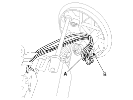
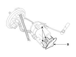
Disconnect the electric pump wiring connector (A) and the fuel sender connector (B).
|
| 3. |
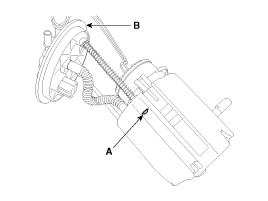
Remove the cushion pipe fixing clip (A), and then separate the head assembly (B) from reservoir cup.
|
| 4. |
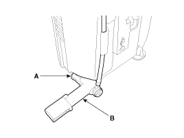
Remove the return nozzle (B) after releasing the fixing hook (A).
|
| 5. |
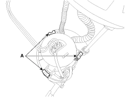
Remove the reservoir-cup after releasing the fixing hooks (A).
|
| 6. |
Remove the pre-filter (B) after releasing the fixing hooks (A).
|

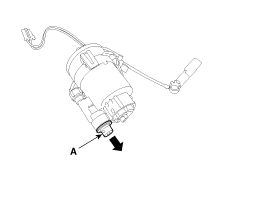
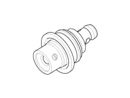
| 7. |
Remove the fuel pressure regulator (A) in the direction.
|
| Installation |
| 1. |
Install in the reverse order of removal. |
Removal 1. Remove the fuel pump. (Refer to Fuel Delivery System - “Fuel Pump”) 2. Disconnect the fuel sender connector (A). 3. Remove the fuel sender (A) after releasing the fix hook.
Description The fuel pump control module (FPCM) is installed on the right side of the fuel tank and controls the DC motor mounted inside the low pressure fuel pump.
Other information:
Kia Cadenza YG 2016-2021 Service Manual: Adaptive Front Lighting System Repair procedures
Removal 1. Disconnect the negative (-) battery terminal. 2. Using a screwdriver or remover, remove the crash pad side cover (A). [RH] 3. Disconnect the stopper (B) from the glove box (A). 4. Disconnect the air damper (A) from the glove box (B).
Kia Cadenza YG 2016-2021 Service Manual: Start/Stop Button Repair procedures
Removal 1. Disconnect the negative (-) battery terminal. 2. Using a screw driver or remover, remove the center fascia lower panel (A). 3. Remove the in-car hose (A) and disconnect the connectors (B) from the heater & A/C control unit. 4.
Categories
- Manuals Home
- Kia Cadenza Owners Manual
- Kia Cadenza Service Manual
- Mode Control Actuator Repair procedures
- Rail Pressure Sensor (RPS) Schematic Diagrams
- Emission Control System
- New on site
- Most important about car
