Kia Cadenza YG: Fuel Delivery System / Fuel Pump Motor Repair procedures
| Removal |
| 1. |
Remove the fuel pump.
(Refer to Fuel Delivery System - “Fuel Pump”) |
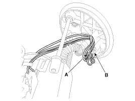
| 2. |
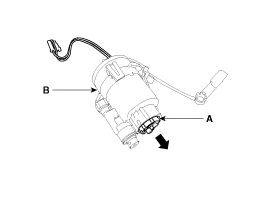
Disconnect the electric pump wiring connector (A) and the fuel sender connector (B).
|
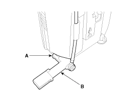
| 3. |
Remove the cushion pipe fixing clip (A), and then separate the head assembly (B) from reservoir cup.
|
| 4. |
Remove the return nozzle (B) after releasing the fixing hook (A).
|
| 5. |
Remove the reservoir-cup after releasing the fixing hooks (A).
|

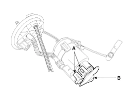
| 6. |
Remove the pre-filter (B) after releasing the fixing hooks (A).
|

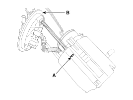
| 7. |
Separate the electric pump motor (A) from the fuel filter (B).
|
| Installation |
| 1. |
Install in the reverse order of removal. |
Removal 1. Remove the fuel pump. (Refer to Fuel Delivery System - “Fuel Pump”) 2. Disconnect the electric pump wiring connector (A) and the fuel sender connector (B).
Removal 1. Remove the fuel pump. (Refer to Fuel Delivery System - “Fuel Pump”) 2. Disconnect the fuel sender connector (A). 3. Remove the fuel sender (A) after releasing the fix hook.
Other information:
Kia Cadenza YG 2016-2021 Service Manual: Photo Sensor Description and Operation
Description 1. The photo sensor is located at the center of defrost nozzle. 2. The photo sensor contains a photovoltaic (sensitive to sunlight) diode. The solar radiation received by its light receiving portion, generates an electromotive force in proportion to the amount of radiation received which is transferred to the automatic tem
Kia Cadenza YG 2016-2021 Service Manual: Mode Control Actuator Repair procedures
Inspection 1. Ignition "OFF” 2. Disconnect the connector of mode control actuator. 3. Verify that the mode control actuator operates to the defrost mode when connecting 12V to the terminal 3and grounding terminal 7. 4. Verify that the mode control actuator operates to the vent mode when connecting in the reverse.
Categories
- Manuals Home
- Kia Cadenza Owners Manual
- Kia Cadenza Service Manual
- Body (Interior and Exterior)
- Suspension System
- Rail Pressure Sensor (RPS) Schematic Diagrams
- New on site
- Most important about car
