Kia Cadenza YG: Fuel Delivery System / Fuel Sender Repair procedures
Kia Cadenza YG 2016-2021 Service Manual / Engine Control / Fuel System / Fuel Delivery System / Fuel Sender Repair procedures
| Removal |
| 1. |
Remove the fuel pump.
(Refer to Fuel Delivery System - “Fuel Pump”) |
| 2. |
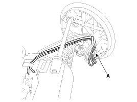
Disconnect the fuel sender connector (A).
|
| 3. |
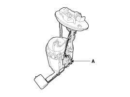
Remove the fuel sender (A) after releasing the fix hook.
|
| Installation |
| 1. |
Install in the reverse order of removal. |
Removal 1. Remove the fuel pump. (Refer to Fuel Delivery System - “Fuel Pump”) 2. Disconnect the electric pump wiring connector (A) and the fuel sender connector (B).
Removal 1. Remove the fuel pump. (Refer to Fuel Delivery System - “Fuel Pump”) 2. Disconnect the electric pump wiring connector (A) and the fuel sender connector (B).
Other information:
Kia Cadenza YG 2016-2021 Service Manual: Repair procedures
Removal 1. Remove the trunk trim in the trunk after removing the screws and clips. (Refer to Body - "Trunk") 2. Remove the camera holder (A) as shown arrow direction, and then remove the back view camera (B). Installation 1. Install the back view camera and camera holder.
Kia Cadenza YG 2016-2021 Service Manual: Specifications
S
Categories
- Manuals Home
- Kia Cadenza Owners Manual
- Kia Cadenza Service Manual
- Body Electrical System
- Driveshaft and axle
- Engine Mechanical System
- New on site
- Most important about car

Copyright © 2026 www.kcadenzavg.com - 0.0256