Kia Cadenza YG: Controller / Heater & A/C Control Unit (DATC) Repair procedures
| Inspection |
| 1. |
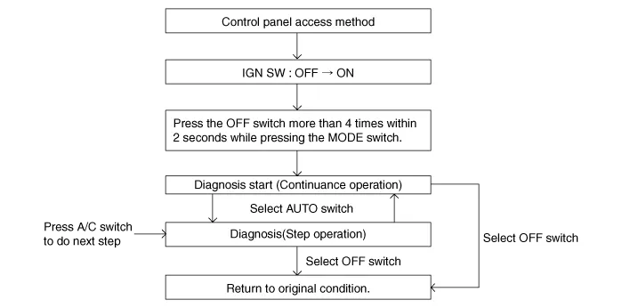
Self-diagnosis process
|
| 2. |
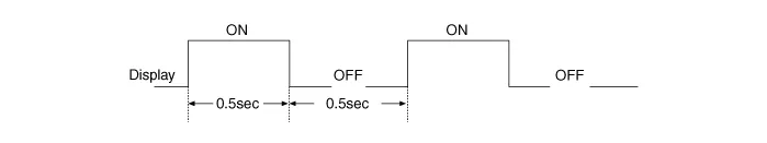
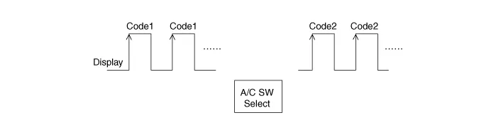
How to read self-diagnostic code.
After the display panel flickers three times every 0.5
second, the corresponding fault code flickers on the setup temperature
display panel every 0.5 second and will show two figures. Codes are
displayed in numerical format
Fault code
|
| 3. |
Fault code display
|

| 4. |
If fault codes are displayed during the check, Inspect malfunction causes by referring to fault codes. |
| 5. |
Fail safe.
|
| Replacement |
| 1. |
Disconnect the negative (-) battery terminal. |
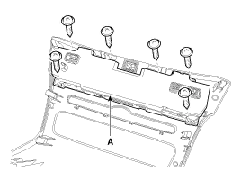
| 2. |
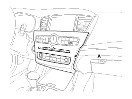
Using a screwdriver or remover, remove the center fascia lower panel (A).
|
| 3. |
Remove the in-car hose (A). |
| 4. |
Disconnect the A/C & heater controller unit connectors (B) from the center fascia lower panel.
|

| 5. |
Loosen the A/C & heater controller unit mounting screws. |
| 6. |
Remove the A/C & heater controller unit (A) from the center fascia lower panel.
|
| 7. |
Install in the reverse order of removal. |
Components (1) [DIGITAL CLOCK TYPE] Connector Pin Function ConnectorPin NoFunctionConnectorPin NoFunctionA1ILL + (TAIL)A31PHOTO SENSOR (-) LEFT2SENSOR REF(+5V)32PHOTO SENSOR (-) RIGHT3HAZARD SIGNAL33HTD4ACC34REAR DEFOG S/W5MODE ACT''R (VENT)35K-LINE6MODE ACT''R (DEF)36-7MODE ACT''R F/B37-8INTAKE ACT''R (FRE)38-9INTAKE ACT''R (REC)39-10INTAKE ACT''R F/B40SENSOR GND11TEMP ACT''R DR (COOL)B1GND12TEMP ACT''R DR (WARM)2-13TEMP ACT''R DR F/B3DEF ACT''R (CLOSE)14TEMP ACT''R PS (COOL)4DEF ACT''R (OPEN)15TEMP ACT''R PS (WARM)5DEF ACT''R F/B16TEMP ACT''R PS F/B6HUMIDITY (PWM)17C_CAN HIGH7-18C_CAN LOW8IGN219DETENT OUT(+)9GND20ILL - (RHEO)10-21ION SIGNAL11BLOWER MOTOR (+)22CLEAN SIGNAL12FET (GATE)23IONIZER DIAGNOSIS13FET (DRAIN F/B)24MM_CAN HIGH14-25MM_CAN LOW15IGN126AMB SENSOR (+)16BATTERY27- 28EVAP SENSOR (+) 29ECV + 30ECV - (GND) Components (2) [ANALOG CLOCK TYPE] Connector Pin Function ConnectorPin NoFunctionConnectorPin NoFunctionA1ILL + (TAIL)A31PHOTO SENSOR (-) LEFT2SENSOR REF(+5V)32PHOTO SENSOR (-) RIGHT3HAZARD SIGNAL33HTD4-34REAR DEFOG S/W5MODE ACT''R (VENT)35K-LINE6MODE ACT''R (DEF)36-7MODE ACT''R F/B37PAB_IGN18INTAKE ACT''R (FRE)38PAB CUT OFF SIGNAL9INTAKE ACT''R (REC)39SBR SIGNAL10INTAKE ACT''R F/B40SENSOR GND11TEMP ACT''R DR (COOL)B1GND12TEMP ACT''R DR (WARM)2-13TEMP ACT''R DR F/B3DEF ACT''R (CLOSE)14TEMP ACT''R PS (COOL)4DEF ACT''R (OPEN)15TEMP ACT''R PS (WARM)5DEF ACT''R F/B16TEMP ACT''R PS F/B6HUMIDITY (PWM)17C_CAN HIGH7-18C_CAN LOW8IGN219DETENT OUT(+)9GND20ILL - (RHEO)10-21ION SIGNAL11BLOWER MOTOR (+)22CLEAN SIGNAL12FET (GATE)23IONIZER DIAGNOSIS13FET (DRAIN F/B)24MM_CAN HIGH14-25MM_CAN LOW15IGN126AMB SENSOR (+)16BATTERY27- 28EVAP SENSOR (+) 29ECV + 30ECV - (GND) Components (3) [UVO TYPE] Connector Pin Function ConnectorPin NoFunctionConnectorPin NoFunctionA1ILL + (TAIL)A31PHOTO SENSOR (-) LEFT2SENSOR REF(+5V)32PHOTO SENSOR (-) RIGHT3HAZARD SIGNAL33HTD4ACC34REAR DEFOG S/W5MODE ACT''R (VENT)35K-LINE6MODE ACT''R (DEF)36-7MODE ACT''R F/B37PAB_IGN18INTAKE ACT''R (FRE)38PAB CUT OFF SIGNAL9INTAKE ACT''R (REC)39SBR SIGNAL10INTAKE ACT''R F/B40SENSOR GND11TEMP ACT''R DR (COOL)B1GND12TEMP ACT''R DR (WARM)2-13TEMP ACT''R DR F/B3DEF ACT''R (CLOSE)14TEMP ACT''R PS (COOL)4DEF ACT''R (OPEN)15TEMP ACT''R PS (WARM)5DEF ACT''R F/B16TEMP ACT''R PS F/B6HUMIDITY (PWM)17C_CAN HIGH7-18C_CAN LOW8IGN219DETENT OUT(+)9GND20ILL - (RHEO)10-21-11BLOWER MOTOR (+)22-12FET (GATE)23-13FET (DRAIN F/B)24-14-25-15IGN126AMB SENSOR (+)16BATTERY27- 28EVAP SENSOR (+) 29ECV + 30ECV - (GND)
Other information:
Kia Cadenza YG 2016-2021 Service Manual: Adaptive Front Lighting System Repair procedures
Removal 1. Disconnect the negative (-) battery terminal. 2. Using a screwdriver or remover, remove the crash pad side cover (A). [RH] 3. Disconnect the stopper (B) from the glove box (A). 4. Disconnect the air damper (A) from the glove box (B).
Kia Cadenza YG 2016-2021 Service Manual: Components and Components Location
C
Categories
- Manuals Home
- Kia Cadenza Owners Manual
- Kia Cadenza Service Manual
- Battery Troubleshooting
- Specifications
- Mode Control Actuator Repair procedures
- New on site
- Most important about car
