Kia Cadenza YG: Engine Control System / Injector Drive Box (IDB) Schematic Diagrams
| IDB terminal and Inoutput |
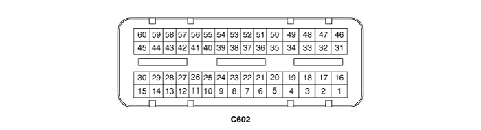
| IDB terminal function |
| Pin No. | Description | Connected to |
| 1 | - | |
| 2 | - | |
| 3 | - | |
| 4 | - | |
| 5 | - | |
| 6 | - | |
| 7 | - | |
| 8 | - | |
| 9 | - | |
| 10 | - | |
| 11 | - | |
| 12 | - | |
| 13 | - | |
| 14 | - | |
| 15 | - | |
| 16 | Injector (Cylinder #3) [Low] control output | Injector (Cylinder #3) |
| 17 | Injector (Cylinder #6) [Low] control output | Injector (Cylinder #6) |
| 18 | Injector (Cylinder #6) [High] control output | Injector (Cylinder #6) |
| 19 | Injector (Cylinder #2) [Low] control output | Injector (Cylinder #2) |
| 20 | Injector (Cylinder #5) [Low] control output | Injector (Cylinder #5) |
| 21 | - | |
| 22 | Injector (Cylinder #2) signal input | Engine Control Module (ECM) |
| 23 | Injector (Cylinder #5) signal input | Engine Control Module (ECM) |
| 24 | - | |
| 25 | Fuel Pressure Control Valve (FPRV) logic input | Engine Control Module (ECM) |
| 26 | CCP-CAN [Low] | Other control module, Data Link Connector (DLC), Multi-purpose check connector |
| 27 | CCP-CAN [High] | Other control module, Data Link Connector (DLC), Multi-purpose check connector |
| 28 | Battery power (B+) | Ignition switch |
| 29 | Battery power (B+) | Main relay |
| 30 | Battery power (B+) | Main relay |
| 31 | Injector (Cylinder #4) [High] control output | Injector (Cylinder #4) |
| 32 | Injector (Cylinder #1) [High] control output | Injector (Cylinder #1) |
| 33 | Injector (Cylinder #3) [High] control output | Injector (Cylinder #3) |
| 34 | Injector (Cylinder #2) [High] control output | Injector (Cylinder #2) |
| 35 | Injector (Cylinder #5) [High] control output | Injector (Cylinder #5) |
| 36 | - | |
| 37 | - | |
| 38 | Injector (Cylinder #3) signal input | Engine Control Module (ECM) |
| 39 | - | |
| 40 | Injector (Cylinder #6) signal input | Engine Control Module (ECM) |
| 41 | Injector (Cylinder #4) signal input | Engine Control Module (ECM) |
| 42 | Battery power (B+) | Ignition switch |
| 43 | Battery power (B+) | Main relay |
| 44 | Battery power (B+) | Main relay |
| 45 | Fuel Pressure Control Valve (FPRV) [High] control output | Fuel Pressure Control Valve (FPRV) |
| 46 | Injector (Cylinder #4) [Low] control output | Injector (Cylinder #4) |
| 47 | Injector (Cylinder #1) [Low] control output | Injector (Cylinder #1) |
| 48 | ECM ground | Chassis ground |
| 49 | ECM ground | Chassis ground |
| 50 | ECM ground | Chassis ground |
| 51 | - | |
| 52 | ECM ground | Chassis ground |
| 53 | ECM ground | Chassis ground |
| 54 | - | |
| 55 | Injector (Cylinder #1) signal input | Engine Control Module (ECM) |
| 56 | - | |
| 57 | - | |
| 58 | - | |
| 59 | Battery power (B+) | Main relay |
| 60 | Fuel Pressure Control Valve (FPRV) [Low] control output | Fuel Pressure Control Valve (FPRV) |
| IDB Terminal input/output signal |
| Pin No. | Description | Condition | Type | Level |
| 1 | - | | | |
| 2 | - | | | |
| 3 | - | | | |
| 4 | - | | | |
| 5 | - | | | |
| 6 | - | | | |
| 7 | - | | | |
| 8 | - | | | |
| 9 | - | | | |
| 10 | - | | | |
| 11 | - | | | |
| 12 | - | | | |
| 13 | - | | | |
| 14 | - | | | |
| 15 | - | | | |
| 16 | Injector (Cylinder #3) [Low] control output | Idle | Pulse | High: Battery voltage |
| Relay ON | Low: Max. 1.0V | |||
| 17 | Injector (Cylinder #6) [Low] control output | Idle | Pulse | High: Battery voltage |
| Relay ON | Low: Max. 1.0V | |||
| 18 | Injector (Cylinder #6) [High] control output | Idle | Pulse | High: Battery voltage ~ 80V |
| Relay ON | Low: Battery voltage | |||
| 19 | Injector (Cylinder #2) [Low] control output | Idle | Pulse | High: Battery voltage |
| Relay ON | Low: Max. 1.0V | |||
| 20 | Injector (Cylinder #5) [Low] control output | Idle | Pulse | High: Battery voltage |
| Relay ON | Low: Max. 1.0V | |||
| 21 | - | | | |
| 22 | Injector (Cylinder #2) signal input | Idle | Pulse | High: Battery voltage |
| Low: Max. 1.0V | ||||
| 23 | Injector (Cylinder #5) signal input | Idle | Pulse | High: Battery voltage |
| Low: Max. 1.0V | ||||
| 24 | - | | | |
| 25 | Fuel Pressure Control Valve (FPRV) logic input | | | |
| | | | ||
| 26 | CCP-CAN [Low] | Recessive | Pulse | 2.0 ~ 3.0V |
| Dominant | 2.75 ~ 4.5V | |||
| 27 | CCP-CAN [High] | Recessive | Pulse | 2.0 ~ 3.0V |
| Dominant | 2.75 ~ 4.5V | |||
| 28 | Battery power (B+) | IG OFF | DC voltage | Max. 0.5V |
| IG ON | Battery voltage | |||
| 29 | Battery power (B+) | IG OFF | DC voltage | Max. 0.5V |
| IG ON | Battery voltage | |||
| 30 | Battery power (B+) | IG OFF | DC voltage | Max. 0.5V |
| IG ON | Battery voltage | |||
| 31 | Injector (Cylinder #4) [High] control output | Idle | Pulse | High: Battery voltage ~ 80V |
| Relay ON | Low: Battery voltage | |||
| 32 | Injector (Cylinder #1) [High] control output | Idle | Pulse | High: Battery voltage ~ 80V |
| Relay ON | Low: Battery voltage | |||
| 33 | Injector (Cylinder #3) [High] control output | Idle | Pulse | High: Battery voltage ~ 80V |
| Relay ON | Low: Battery voltage | |||
| 34 | Injector (Cylinder #2) [High] control output | Idle | Pulse | High: Battery voltage ~ 80V |
| Relay ON | Low: Battery voltage | |||
| 35 | Injector (Cylinder #5) [High] control output | Idle | Pulse | High: Battery voltage ~ 80V |
| Relay ON | Low: Battery voltage | |||
| 36 | - | | | |
| 37 | - | | | |
| 38 | Injector (Cylinder #3) signal input | Idle | Pulse | High: Battery voltage |
| Low: Max. 1.0V | ||||
| 39 | - | | | |
| 40 | Injector (Cylinder #6) signal input | Idle | Pulse | High: Battery voltage |
| Low: Max. 1.0V | ||||
| 41 | Injector (Cylinder #4) signal input | Idle | Pulse | High: Battery voltage |
| Low: Max. 1.0V | ||||
| 42 | Battery power (B+) | IG OFF | DC voltage | Max. 0.5V |
| IG ON | Battery voltage | |||
| 43 | Battery power (B+) | IG OFF | DC voltage | Max. 0.5V |
| IG ON | Battery voltage | |||
| 44 | Battery power (B+) | IG OFF | DC voltage | Max. 0.5V |
| IG ON | Battery voltage | |||
| 45 | Fuel Pressure Control Valve (FPRV) [High] control output | Idle | DC voltage | Battery voltage |
| Max. 1.0V | ||||
| 46 | Injector (Cylinder #4) [Low] control output | Idle | Pulse | High: Battery voltage |
| Relay ON | Low: Max. 1.0V | |||
| 47 | Injector (Cylinder #1) [Low] control output | Idle | Pulse | High: Battery voltage |
| Relay ON | Low: Max. 1.0V | |||
| 48 | ECM ground | Idle | DC voltage | Max. 50mV |
| 49 | ECM ground | Idle | DC voltage | Max. 50mV |
| 50 | ECM ground | Idle | DC voltage | Max. 50mV |
| 51 | - | | | |
| 52 | ECM ground | Idle | DC voltage | Max. 50mV |
| 53 | ECM ground | Idle | DC voltage | Max. 50mV |
| 54 | - | | | |
| 55 | Injector (Cylinder #1) signal input | Idle | Pulse | High: Battery voltage |
| Low: Max. 1.0V | ||||
| 56 | - | | | |
| 57 | - | | | |
| 58 | - | | | |
| 59 | Battery power (B+) | IG OFF | DC voltage | Max. 0.5V |
| IG ON | Battery voltage | |||
| 60 | Fuel Pressure Control Valve (FPRV) [Low] control output | Idle | DC voltage | Battery voltage |
| Max. 1.0V |
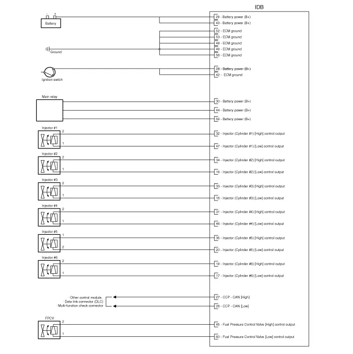
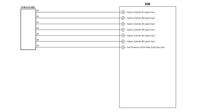
| Circuit Diagram |
Removal When replacing the ECM, the vehicle equipped with the immobilizer must be performed procedure as below. [In the case of installing used ECM] 1) Perform "ECM Neutral mode" procedure with GDS.
Removal 1. Turn the ignition switch off and disconnect the battery negative (-) cable. 2. Disconnect the injector drive box (IDB) connector (A).
Other information:
Kia Cadenza YG 2016-2021 Service Manual: Surround View Monitoring Unit Repair procedures
Removal 1. Disconnect the negative (-) battery terminal. 2. Remove the glove box housing. (Refer to Body - "Glove Box Housing") 3. Remove the SVM unit (B) after disconnecting the connectors (A) and mounting bolts. Installation 1. Install the SVM unit.
Kia Cadenza YG 2016-2021 Service Manual: A/C Pressure Transducer Description and Operation
Description A/C pressure transducer convert the pressure value of high pressure line into voltage value after measure it. By converted voltage value, engine ECU controls cooling fan by operating it high speed or low speed. Engine ECU stop the operation of compressor when the temperature of refrigerant line is so high or so low irregularl
Categories
- Manuals Home
- Kia Cadenza Owners Manual
- Kia Cadenza Service Manual
- Engine Electrical System
- Timing Chain Repair procedures
- General Information
- New on site
- Most important about car
