Kia Cadenza YG: Engine Control System / Engine Control Module (ECM) Repair procedures
| Removal |
When replacing the ECM, the vehicle equipped with the immobilizer must be performed procedure as below.
[In the case of installing used ECM]
[In the case of installing new ECM]
Perform "Key teaching" procedure with GDS.
(Refer to Body Electrical System - "Immobilizer System")
|

When replacing the ECM, the vehicle equipped with the smart key system (Button start) must be performed procedure as below.
[In the case of installing used ECM]
[In the case of installing new ECM]
Insert the key (or press the start button) and turn it to the
IGN ON and OFF position. Then the ECM learns the smart key information
automatically.
|
| 1. |
Turn ignition switch OFF and disconnect the negative (-) battery cable. |
| 2. |
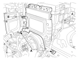
Remove the cover. |
| 3. |
Disconnect the ECM connector (A).
|

| 4. |
Remove the air cleaner assembly.
(Refer to Engine Mechanical System - "Air cleaner" ) |
| 5. |
Remove the battery tray.
(Refer to Engine Electrical System - "Battery") |
| 6. |
Remove the ECM bracket installation bolts (A) and nut (B).
|
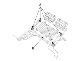
| 7. |
After removing the installation nuts (A), remove the ECM (B) from the bracket.
|
| Installation |
When replacing the ECM, the vehicle equipped with the immobilizer must be performed procedure as below.
[In the case of installing used ECM]
[In the case of installing new ECM]
Perform "Key teaching" procedure with GDS.
(Refer to Body Electrical System - "Immobilizer System")
|
When replacing the ECM, the vehicle equipped with the smart key system (Button start) must be performed procedure as below.
[In the case of installing used ECM]
[In the case of installing new ECM]
Insert the key (or press the start button) and turn it to the
IGN ON and OFF position. Then the ECM learns the smart key information
automatically.
|
| 1. |
Install in the reverse order of removal.
|
| ECM Problem Inspection Procedure |
| 1. |
TEST ECM GROUND CIRCUIT: Measure resistance between ECM and
chassis ground using the backside of ECM harness connector as ECM side
check point. If the problem is found, repair it.
|
| 2. |
TEST ECM CONNECTOR: Disconnect the ECM connector and visually
check the ground terminals on ECM side and harness side for bent pins
or poor contact pressure. If the problem is found, repair it. |
| 3. |
If problem is not found in Step 1 and 2, the ECM could be
faulty. If so, replace the ECM with a new one, and then check the
vehicle again. If the vehicle operates normally then the problem was
likely with the ECM. |
| 4. |
RE-TEST THE ORIGINAL ECM: Install the original ECM (may be
broken) into a known-good vehicle and check the vehicle. If the problem
occurs again, replace the original ECM with a new one. If problem does
not occur, this is intermittent problem.
(Refer to “Intermittent Problem Inspection Procedure” in Basic Inspection Procedure)
|
The programmed VIN cannot be changed. When writing the VIN, confirm the VIN carefully |
| 1. |
Select "VIN Writing" function in "Vehicle S/W Management". |
| 2. |
Select "Write VIN" in "ID Register".
|
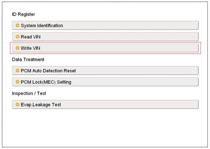
| 3. |
Input the VIN.
|

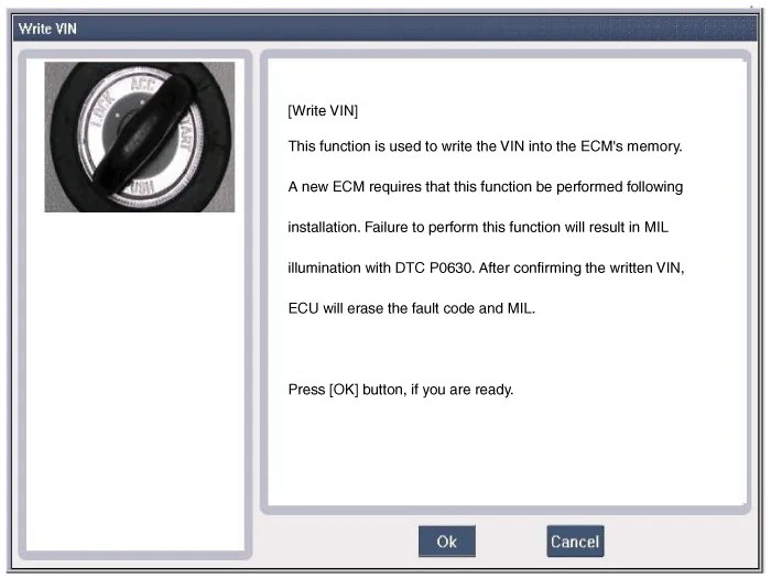
| 4. |
Turn the ignition switch OFF, then back ON. |
ECM Terminal And Input/Output signal ECM Terminal Function Connector [E600-A] Pin No.DescriptionConnected to1- 2- 3- 4Immobilizer Lamp control outputImmobilizer Lamp [Without Button Engine Start System]5Power groundChassis Ground6Power groundChassis Ground7- 8- 92nd CAN [High]Multi-Purpose Check Connector10CAN [High]Other control module, Data Link Connector (DLC), Multi-Purpose Check Connector11Fuel Tank Pressure Sensor (FTPS) signal inputFuel Tank Pressure Sensor (FTPS)12Electrical Load signal inputHead Lamp Relay13- 14Sensor power (+5V)Accelerator Position Sensor (APS) 115Sensor power (+5V)A/C Pressure Transducer (APT)Rail Pressure Sensor (RPS)16Fuel Level Sender (FLS) signal inputFuel Level Sender (FLS)17-18- 19- 20A/C Compressor relay signal outputA/C Control Module21Brake Switch 2 signal inputBrake Switch22- 23- 24Alternator PWM signal input [FR]Alternator25-26- 27Battery power (B+)Ignition Switch28Rail Pressure Sensor (RPS) signal inputRail Pressure Sensor (RPS)29- 30Power groundChassis Ground31- 32- 33- 342nd CAN [Low]Multi-Purpose Check Connector35CAN [Low]Other control module, Data Link Connector (DLC), Multi-Purpose Check Connector36- 37Sensor groundRail Pressure Sensor (RPS)38Accelerator Position Sensor (APS) 1 signal inputAccelerator Position Sensor (APS) 139- 40- 41-42A/C Switch "ON" signal inputA/C Control Module43Brake Switch 1 signal inputBrake Switch44- 45- 46- 47- 48-49- 50- 51- 52Battery power (B+)Battery53- 54- 55Power groundChassis Ground56- 57A/C Compressor Clutch Relay control outputA/C Control Module [With Immobilzer]58- 59Sensor groundAccelerator Position Sensor (APS) 260Sensor groundAccelerator Position Sensor (APS) 161Sensor groundFuel Tank Pressure Sensor (FTPS)62GroundCruise Control Switch63Sensor groundA/C Pressure Transducer (APT)64- 65Sensor Power (+5V)Fuel Tank Pressure Sensor (FTPS)66Cruise Control Switch signal inputCruise Control Switch67A/C Pressure Transducer (APT) signal inputA/C Pressure Transducer (APT)68Accelerator Position Sensor (APS) 2 signal inputAccelerator Position Sensor (APS) 269-70Engine speed signal outputPower Distribution Module (PDM)71Cooling Fan Relay [High] control outputCooling Fan Relay [High]72Alternator PWM signal output (COM)Alternator73- 74Immobilizer communication lineSmart Key Control Module [With Button Engine Start System]Immobilizer Control Unit [Without Button Engine Start System]75Battery power (B+)Main Relay76- 77Battery power (B+)Battery78-79- 80Power groundChassis ground81- 82- 83- 84- 85- 86- 87LIN (Local Interconnect Network) Serial Bus LineBattery Sensor88- 89- 90Sensor power (+5V)Accelerator Position Sensor (APS) 291Cooling Fan Relay [Low] control outputCooling Fan Relay [Low]92- 93Starter Relay control outputStarter Relay94Main Relay control outputMain Relay95Fuel pump Relay control outputFuel pump Relay 96Canister Close Valve (CCV) control outputCanister Close Valve (CCV)97- 98- 99Battery power (B+)Main Relay100Battery power (B+)Main Relay Connector [C600-B] Pin No.
IDB terminal and Inoutput IDB terminal function Connector [C602] Pin No.DescriptionConnected to1- 2- 3- 4- 5- 6- 7- 8- 9- 10- 11- 12- 13- 14- 15- 16Injector (Cylinder #3) [Low] control outputInjector (Cylinder #3)17Injector (Cylinder #6) [Low] control outputInjector (Cylinder #6)18Injector (Cylinder #6) [High] control outputInjector (Cylinder #6)19Injector (Cylinder #2) [Low] control outputInjector (Cylinder #2)20Injector (Cylinder #5) [Low] control outputInjector (Cylinder #5)21- 22Injector (Cylinder #2) signal inputEngine Control Module (ECM)23Injector (Cylinder #5) signal inputEngine Control Module (ECM)24- 25Fuel Pressure Control Valve (FPRV) logic inputEngine Control Module (ECM)26CCP-CAN [Low]Other control module, Data Link Connector (DLC), Multi-purpose check connector27CCP-CAN [High]Other control module, Data Link Connector (DLC), Multi-purpose check connector28Battery power (B+)Ignition switch29Battery power (B+)Main relay30Battery power (B+)Main relay31Injector (Cylinder #4) [High] control outputInjector (Cylinder #4)32Injector (Cylinder #1) [High] control outputInjector (Cylinder #1)33Injector (Cylinder #3) [High] control outputInjector (Cylinder #3)34Injector (Cylinder #2) [High] control outputInjector (Cylinder #2)35Injector (Cylinder #5) [High] control outputInjector (Cylinder #5)36- 37- 38Injector (Cylinder #3) signal inputEngine Control Module (ECM)39- 40Injector (Cylinder #6) signal inputEngine Control Module (ECM)41Injector (Cylinder #4) signal inputEngine Control Module (ECM)42Battery power (B+)Ignition switch43Battery power (B+)Main relay44Battery power (B+)Main relay45Fuel Pressure Control Valve (FPRV) [High] control outputFuel Pressure Control Valve (FPRV)46Injector (Cylinder #4) [Low] control outputInjector (Cylinder #4)47Injector (Cylinder #1) [Low] control outputInjector (Cylinder #1)48ECM groundChassis ground49ECM groundChassis ground50ECM groundChassis ground51- 52ECM groundChassis ground53ECM groundChassis ground54- 55Injector (Cylinder #1) signal inputEngine Control Module (ECM)56- 57- 58- 59Battery power (B+)Main relay60Fuel Pressure Control Valve (FPRV) [Low] control outputFuel Pressure Control Valve (FPRV) IDB Terminal input/output signal Connector [C602] Pin No.
Other information:
Kia Cadenza YG 2016-2021 Service Manual: Description and Operation
Description Surround View Monitoring System (SVM) is the system that allows video monitoring of 360 degrees around the vehicle. The system includes 4 ultra optical camera mounted around the vehicle (front, both sides, rear). The video from these cameras are applied with distortion compensation, time point conversion, and video merging
Kia Cadenza YG 2016-2021 Service Manual: Components and Components Location
C
Categories
- Manuals Home
- Kia Cadenza Owners Manual
- Kia Cadenza Service Manual
- Transaxle Control Module (TCM) Repair procedures
- Schematic Diagrams
- Emission Control System
- New on site
- Most important about car
