Kia Cadenza YG: Engine Control System / Injector Drive Box (IDB) Schematic Diagrams
| IDB terminal and Inoutput |
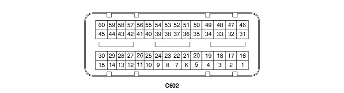
| IDB terminal function |
| Pin No. | Description | Connected to |
| 1 | - | |
| 2 | - | |
| 3 | - | |
| 4 | - | |
| 5 | - | |
| 6 | - | |
| 7 | - | |
| 8 | - | |
| 9 | - | |
| 10 | - | |
| 11 | - | |
| 12 | - | |
| 13 | - | |
| 14 | - | |
| 15 | - | |
| 16 | Injector (Cylinder #3) [Low] control output | Injector (Cylinder #3) |
| 17 | Injector (Cylinder #6) [Low] control output | Injector (Cylinder #6) |
| 18 | Injector (Cylinder #6) [High] control output | Injector (Cylinder #6) |
| 19 | Injector (Cylinder #2) [Low] control output | Injector (Cylinder #2) |
| 20 | Injector (Cylinder #5) [Low] control output | Injector (Cylinder #5) |
| 21 | - | |
| 22 | Injector (Cylinder #2) signal input | Engine Control Module (ECM) |
| 23 | Injector (Cylinder #5) signal input | Engine Control Module (ECM) |
| 24 | - | |
| 25 | Fuel Pressure Control Valve (FPRV) logic input | Engine Control Module (ECM) |
| 26 | CCP-CAN [Low] | Other control module, Data Link Connector (DLC), Multi-purpose check connector |
| 27 | CCP-CAN [High] | Other control module, Data Link Connector (DLC), Multi-purpose check connector |
| 28 | Battery power (B+) | Ignition switch |
| 29 | Battery power (B+) | Main relay |
| 30 | Battery power (B+) | Main relay |
| 31 | Injector (Cylinder #4) [High] control output | Injector (Cylinder #4) |
| 32 | Injector (Cylinder #1) [High] control output | Injector (Cylinder #1) |
| 33 | Injector (Cylinder #3) [High] control output | Injector (Cylinder #3) |
| 34 | Injector (Cylinder #2) [High] control output | Injector (Cylinder #2) |
| 35 | Injector (Cylinder #5) [High] control output | Injector (Cylinder #5) |
| 36 | - | |
| 37 | - | |
| 38 | Injector (Cylinder #3) signal input | Engine Control Module (ECM) |
| 39 | - | |
| 40 | Injector (Cylinder #6) signal input | Engine Control Module (ECM) |
| 41 | Injector (Cylinder #4) signal input | Engine Control Module (ECM) |
| 42 | Battery power (B+) | Ignition switch |
| 43 | Battery power (B+) | Main relay |
| 44 | Battery power (B+) | Main relay |
| 45 | Fuel Pressure Control Valve (FPRV) [High] control output | Fuel Pressure Control Valve (FPRV) |
| 46 | Injector (Cylinder #4) [Low] control output | Injector (Cylinder #4) |
| 47 | Injector (Cylinder #1) [Low] control output | Injector (Cylinder #1) |
| 48 | ECM ground | Chassis ground |
| 49 | ECM ground | Chassis ground |
| 50 | ECM ground | Chassis ground |
| 51 | - | |
| 52 | ECM ground | Chassis ground |
| 53 | ECM ground | Chassis ground |
| 54 | - | |
| 55 | Injector (Cylinder #1) signal input | Engine Control Module (ECM) |
| 56 | - | |
| 57 | - | |
| 58 | - | |
| 59 | Battery power (B+) | Main relay |
| 60 | Fuel Pressure Control Valve (FPRV) [Low] control output | Fuel Pressure Control Valve (FPRV) |
| IDB Terminal input/output signal |
| Pin No. | Description | Condition | Type | Level |
| 1 | - | | | |
| 2 | - | | | |
| 3 | - | | | |
| 4 | - | | | |
| 5 | - | | | |
| 6 | - | | | |
| 7 | - | | | |
| 8 | - | | | |
| 9 | - | | | |
| 10 | - | | | |
| 11 | - | | | |
| 12 | - | | | |
| 13 | - | | | |
| 14 | - | | | |
| 15 | - | | | |
| 16 | Injector (Cylinder #3) [Low] control output | Idle | Pulse | High: Battery voltage |
| Relay ON | Low: Max. 1.0V | |||
| 17 | Injector (Cylinder #6) [Low] control output | Idle | Pulse | High: Battery voltage |
| Relay ON | Low: Max. 1.0V | |||
| 18 | Injector (Cylinder #6) [High] control output | Idle | Pulse | High: Battery voltage ~ 80V |
| Relay ON | Low: Battery voltage | |||
| 19 | Injector (Cylinder #2) [Low] control output | Idle | Pulse | High: Battery voltage |
| Relay ON | Low: Max. 1.0V | |||
| 20 | Injector (Cylinder #5) [Low] control output | Idle | Pulse | High: Battery voltage |
| Relay ON | Low: Max. 1.0V | |||
| 21 | - | | | |
| 22 | Injector (Cylinder #2) signal input | Idle | Pulse | High: Battery voltage |
| Low: Max. 1.0V | ||||
| 23 | Injector (Cylinder #5) signal input | Idle | Pulse | High: Battery voltage |
| Low: Max. 1.0V | ||||
| 24 | - | | | |
| 25 | Fuel Pressure Control Valve (FPRV) logic input | | | |
| | | | ||
| 26 | CCP-CAN [Low] | Recessive | Pulse | 2.0 ~ 3.0V |
| Dominant | 2.75 ~ 4.5V | |||
| 27 | CCP-CAN [High] | Recessive | Pulse | 2.0 ~ 3.0V |
| Dominant | 2.75 ~ 4.5V | |||
| 28 | Battery power (B+) | IG OFF | DC voltage | Max. 0.5V |
| IG ON | Battery voltage | |||
| 29 | Battery power (B+) | IG OFF | DC voltage | Max. 0.5V |
| IG ON | Battery voltage | |||
| 30 | Battery power (B+) | IG OFF | DC voltage | Max. 0.5V |
| IG ON | Battery voltage | |||
| 31 | Injector (Cylinder #4) [High] control output | Idle | Pulse | High: Battery voltage ~ 80V |
| Relay ON | Low: Battery voltage | |||
| 32 | Injector (Cylinder #1) [High] control output | Idle | Pulse | High: Battery voltage ~ 80V |
| Relay ON | Low: Battery voltage | |||
| 33 | Injector (Cylinder #3) [High] control output | Idle | Pulse | High: Battery voltage ~ 80V |
| Relay ON | Low: Battery voltage | |||
| 34 | Injector (Cylinder #2) [High] control output | Idle | Pulse | High: Battery voltage ~ 80V |
| Relay ON | Low: Battery voltage | |||
| 35 | Injector (Cylinder #5) [High] control output | Idle | Pulse | High: Battery voltage ~ 80V |
| Relay ON | Low: Battery voltage | |||
| 36 | - | | | |
| 37 | - | | | |
| 38 | Injector (Cylinder #3) signal input | Idle | Pulse | High: Battery voltage |
| Low: Max. 1.0V | ||||
| 39 | - | | | |
| 40 | Injector (Cylinder #6) signal input | Idle | Pulse | High: Battery voltage |
| Low: Max. 1.0V | ||||
| 41 | Injector (Cylinder #4) signal input | Idle | Pulse | High: Battery voltage |
| Low: Max. 1.0V | ||||
| 42 | Battery power (B+) | IG OFF | DC voltage | Max. 0.5V |
| IG ON | Battery voltage | |||
| 43 | Battery power (B+) | IG OFF | DC voltage | Max. 0.5V |
| IG ON | Battery voltage | |||
| 44 | Battery power (B+) | IG OFF | DC voltage | Max. 0.5V |
| IG ON | Battery voltage | |||
| 45 | Fuel Pressure Control Valve (FPRV) [High] control output | Idle | DC voltage | Battery voltage |
| Max. 1.0V | ||||
| 46 | Injector (Cylinder #4) [Low] control output | Idle | Pulse | High: Battery voltage |
| Relay ON | Low: Max. 1.0V | |||
| 47 | Injector (Cylinder #1) [Low] control output | Idle | Pulse | High: Battery voltage |
| Relay ON | Low: Max. 1.0V | |||
| 48 | ECM ground | Idle | DC voltage | Max. 50mV |
| 49 | ECM ground | Idle | DC voltage | Max. 50mV |
| 50 | ECM ground | Idle | DC voltage | Max. 50mV |
| 51 | - | | | |
| 52 | ECM ground | Idle | DC voltage | Max. 50mV |
| 53 | ECM ground | Idle | DC voltage | Max. 50mV |
| 54 | - | | | |
| 55 | Injector (Cylinder #1) signal input | Idle | Pulse | High: Battery voltage |
| Low: Max. 1.0V | ||||
| 56 | - | | | |
| 57 | - | | | |
| 58 | - | | | |
| 59 | Battery power (B+) | IG OFF | DC voltage | Max. 0.5V |
| IG ON | Battery voltage | |||
| 60 | Fuel Pressure Control Valve (FPRV) [Low] control output | Idle | DC voltage | Battery voltage |
| Max. 1.0V |
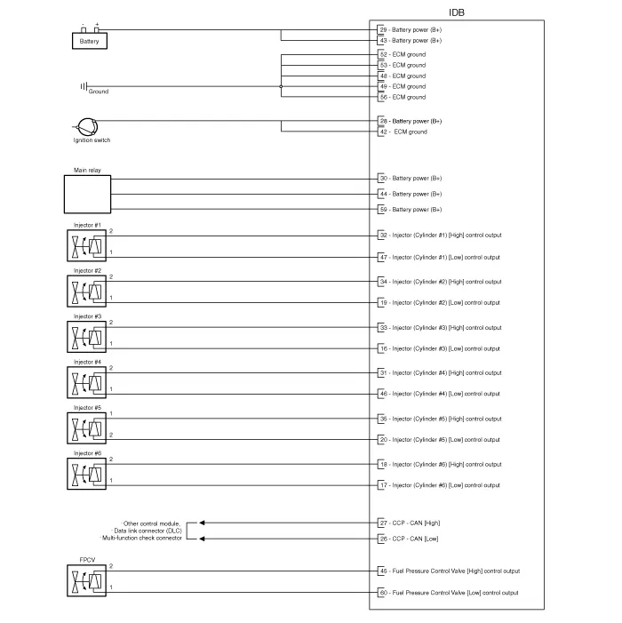
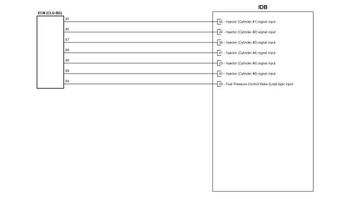
| Circuit Diagram |
Removal When replacing the ECM, the vehicle equipped with the immobilizer must be performed procedure as below. [In the case of installing used ECM] 1) Perform "ECM Neutral mode" procedure with GDS.
Removal 1. Turn the ignition switch off and disconnect the battery negative (-) cable. 2. Disconnect the injector drive box (IDB) connector (A).
Other information:
Kia Cadenza YG 2016-2021 Service Manual: Repair procedures
Inspection Initialization and diagnosis sequence by using diagnostic equipment Below content summarize the procedure for A/S using Diagnostic equipment Download Parameter 1. Select "AFLS" menu after selecting a vehicle. 2. Select "Parameter download" menu for define a characteristc of vehicle.
Kia Cadenza YG 2016-2021 Service Manual: Mode Control Actuator Repair procedures
Inspection 1. Ignition "OFF” 2. Disconnect the connector of mode control actuator. 3. Verify that the mode control actuator operates to the defrost mode when connecting 12V to the terminal 3and grounding terminal 7. 4. Verify that the mode control actuator operates to the vent mode when connecting in the reverse.
Categories
- Manuals Home
- Kia Cadenza Owners Manual
- Kia Cadenza Service Manual
- Engine Mechanical System
- Specifications
- Automatic Transaxle System
- New on site
- Most important about car
