Kia Cadenza YG: Engine Control System / Injector Drive Box (IDB) Repair procedures
| Removal |
| 1. |
Turn the ignition switch off and disconnect the battery negative (-) cable. |
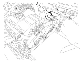
| 2. |
Disconnect the injector drive box (IDB) connector (A).
|
| 3. |
Remove the air cleaner assembly.
(Refer to Engine Mechanical System - "Air Cleaner") |
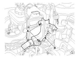
| 4. |
Remove the main wiring harness (B) after removing the nut (A).
|
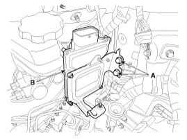
| 5. |
Remove the IDB bracket assembly (B) after removing the bolts (A).
|
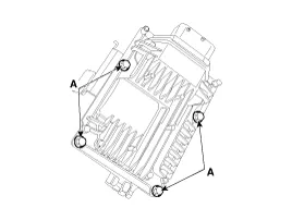
| 6. |
After removing the installation bolts (A), remove the IDB from the bracket.
|
| Installation |
| 1. |
Install in the reverse order of removal.
|
IDB terminal and Inoutput IDB terminal function Connector [C602] Pin No.DescriptionConnected to1- 2- 3- 4- 5- 6- 7- 8- 9- 10- 11- 12- 13- 14- 15- 16Injector (Cylinder #3) [Low] control outputInjector (Cylinder #3)17Injector (Cylinder #6) [Low] control outputInjector (Cylinder #6)18Injector (Cylinder #6) [High] control outputInjector (Cylinder #6)19Injector (Cylinder #2) [Low] control outputInjector (Cylinder #2)20Injector (Cylinder #5) [Low] control outputInjector (Cylinder #5)21- 22Injector (Cylinder #2) signal inputEngine Control Module (ECM)23Injector (Cylinder #5) signal inputEngine Control Module (ECM)24- 25Fuel Pressure Control Valve (FPRV) logic inputEngine Control Module (ECM)26CCP-CAN [Low]Other control module, Data Link Connector (DLC), Multi-purpose check connector27CCP-CAN [High]Other control module, Data Link Connector (DLC), Multi-purpose check connector28Battery power (B+)Ignition switch29Battery power (B+)Main relay30Battery power (B+)Main relay31Injector (Cylinder #4) [High] control outputInjector (Cylinder #4)32Injector (Cylinder #1) [High] control outputInjector (Cylinder #1)33Injector (Cylinder #3) [High] control outputInjector (Cylinder #3)34Injector (Cylinder #2) [High] control outputInjector (Cylinder #2)35Injector (Cylinder #5) [High] control outputInjector (Cylinder #5)36- 37- 38Injector (Cylinder #3) signal inputEngine Control Module (ECM)39- 40Injector (Cylinder #6) signal inputEngine Control Module (ECM)41Injector (Cylinder #4) signal inputEngine Control Module (ECM)42Battery power (B+)Ignition switch43Battery power (B+)Main relay44Battery power (B+)Main relay45Fuel Pressure Control Valve (FPRV) [High] control outputFuel Pressure Control Valve (FPRV)46Injector (Cylinder #4) [Low] control outputInjector (Cylinder #4)47Injector (Cylinder #1) [Low] control outputInjector (Cylinder #1)48ECM groundChassis ground49ECM groundChassis ground50ECM groundChassis ground51- 52ECM groundChassis ground53ECM groundChassis ground54- 55Injector (Cylinder #1) signal inputEngine Control Module (ECM)56- 57- 58- 59Battery power (B+)Main relay60Fuel Pressure Control Valve (FPRV) [Low] control outputFuel Pressure Control Valve (FPRV) IDB Terminal input/output signal Connector [C602] Pin No.
Description The Electronic Throttle Control (ETC) System consists of a throttle body with an integrated control motor and throttle position sensor (TPS).
Other information:
Kia Cadenza YG 2016-2021 Service Manual: Components and Components Location
C
Kia Cadenza YG 2016-2021 Service Manual: Blind Spot Detection Unit Repair procedures
Removal 1. Disconnect the negative (-) battery terminal. 2. Remove the rear bumper. (Refer to Body - "Rear Bumper") 3. Remove the BSD unit (A) after loosening the mounting screws. Take care not to separate the bracket from rear bumper when removing the BSD sensor.
Categories
- Manuals Home
- Kia Cadenza Owners Manual
- Kia Cadenza Service Manual
- General Information
- Brake System
- Body (Interior and Exterior)
- New on site
- Most important about car
