Kia Cadenza YG: Engine Control System / ETC (Electronic Throttle Control) System Description and Operation
Kia Cadenza YG 2016-2021 Service Manual / Engine Control / Fuel System / Engine Control System / ETC (Electronic Throttle Control) System Description and Operation
| Description |
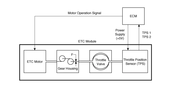
The Electronic Throttle Control (ETC) System consists of a
throttle body with an integrated control motor and throttle position
sensor (TPS). Instead of the traditional throttle cable, an Accelerator
Position Sensor (APS) is used to receive driver input. The ECM uses the
APS signal to calculate the target throttle angle; the position of the
throttle is then adjusted via ECM control of the ETC motor. The TPS
signal is used to provide feedback regarding throttle position to the
ECM. Using ETC, precise control over throttle position is possible; the
need for external cruise control modules/cables is eliminated.


| 1. Dry bearing 2. DC motor 3. Non-contact hall sensor 4. Gear | 5. Magnet 6. Hall IC 7. Yoke 8. Stator |
| Schematic Diagram |
Removal 1. Turn the ignition switch off and disconnect the battery negative (-) cable. 2. Disconnect the injector drive box (IDB) connector (A).
Fail-Safe Mode ItemFail-SafeETC MotorThrottle valve stuck at 7°TPSTPS 1 faultECM looks at TPS2TPS 2 faultECM looks at TPS1TPS 1,2 faultThrottle valve stuck at 7°APSAPS 1 faultECM looks at APS 2APS 2 faultECM looks at APS 1APS 1,2 faultEngine idle state When throttle value is stuck at 7°, engine speed is limited at below 1,500rpm and vehicle speed at maximum 40 ~ 50 km/h (25 ~ 31 mph)
Categories
- Manuals Home
- Kia Cadenza Owners Manual
- Kia Cadenza Service Manual
- Emission Control System
- Schematic Diagrams
- Brake System
- New on site
- Most important about car

Copyright © 2026 www.kcadenzavg.com - 0.0212