Kia Cadenza YG: Automatic Transaxle Control System / Input Speed Sensor Repair procedures
| Inspection |
| 1. |
Turn ignition switch OFF. |
| 2. |
Remove the battery and battery tray.
(Refer to Engine Electrical System - "Battery") |
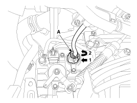
| 3. |
Disconnect the solenoid valve connector (A).
|
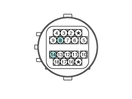
| 4. |
Measure the resistance between power terminal (14) and signal terminal (8).
|
| Removal |
| 1. |
Remove the valve body assembly.
(Refer to Hydraulic System - "Valve Body") |
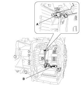
| 2. |
Disconnect the input & output speed sensor connector (A). |
| 3. |
Remove the input & output speed sensor (B) after loosening the bolts.
|
| Installation |
| 1. |
Install in the reverse order of removal.
|

Signal Waveform Fig 1) Input/Output speed sensor at low speed Fig 2) Input/Output speed sensor at high speed
Description The output speed sensor is a vital unit that measures the rate of rotation of the transaxle''s turbine shaft and output shaft, and delivers the readings to the Transaxle Control Module(TCM).
Other information:
Kia Cadenza YG 2016-2021 Service Manual: Pantoscopic Camera Repair procedures
Removal Front Pantoscopic Camera 1. Disconnect the negative (-) battery terminal. 2. Remove the front bumper cover. (Refer to Body - "Front Bumper Cover") 3. Remove the pantocscpic camera (B) after loosening the mounting screws and connector (A).
Kia Cadenza YG 2016-2021 Service Manual: Ambient Sensor Repair procedures
Inspection 1. Ignition "OFF" 2. Disconnect ambient temperature sensor. 3. Check the resistance of ambient temperature sensor between terminals 1 and 2 whether it is changed by changing of the ambient temperature. 1. Sensor Ground2.
Categories
- Manuals Home
- Kia Cadenza Owners Manual
- Kia Cadenza Service Manual
- Schematic Diagrams
- Automatic Transaxle System
- Rail Pressure Sensor (RPS) Schematic Diagrams
- New on site
- Most important about car
