Kia Cadenza YG: Automatic Transaxle Control System / Input Speed Sensor Schematic Diagrams
| Circuit Diagram |
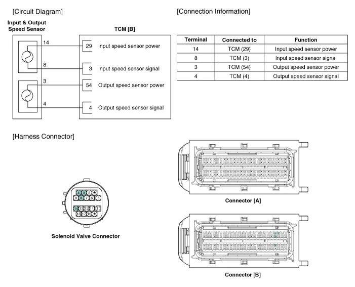
Specifications ▷ Type: Hall effect sensor Operation condition [°C(°F)]((-)40~150)) -40~302Air gap(mm)in.(0.95~1.65)0.037~0.065Output voltage(V)High1.
Signal Waveform Fig 1) Input/Output speed sensor at low speed Fig 2) Input/Output speed sensor at high speed
Other information:
Kia Cadenza YG 2016-2021 Service Manual: Description and Operation
System Overview RPAS (Rear Parking Assist System) is an electronic driving aid that warns the driver to be cautious while parking or in low speed environments. The sensor uses ultrasonic waves to detect objects within proximity of the vehicle.
Kia Cadenza YG 2016-2021 Service Manual: Intake Actuator Repair procedures
Inspection 1. Ignition "OFF". 2. Disconnect the intake actuator connector. 3. Verify that the actuator operates to the recirculation position when connecting 12V to the terminal 3 and grounding terminal 7. 4. Verify that the intake actuator operates to the fresh position when connecting in the reverse.
Categories
- Manuals Home
- Kia Cadenza Owners Manual
- Kia Cadenza Service Manual
- Schematic Diagrams
- Restraint
- Alternator Schematic Diagrams
- New on site
- Most important about car
