Kia Cadenza YG: Automatic Transaxle Control System / 35R Clutch Control Solenoid Valve(35R/C_VFS) Repair procedures
Kia Cadenza YG 2016-2021 Service Manual / Automatic Transaxle System / Automatic Transaxle Control System / 35R Clutch Control Solenoid Valve(35R/C_VFS) Repair procedures
| Inspection |
| 1. |
Turn ignition switch OFF. |
| 2. |
Remove the battery and battery tray.
(Refer to Engine Electrical System - "Battery") |
| 3. |
Disconnect the solenoid valve connector (A).
|
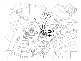
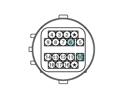
| 4. |
Measure the resistance between power terminal (10) and signal terminal (6).
|
| Replacement |
If a solenoid valve of VFS type needs to be replaced, the
valve body assembly should be replaced and the oil pressure should be
adjusted. If the solenoid valve is replaced individually, it is not
possible to adjust the oil pressure without additional equipment, and if
the oil pressure adjustment procedure is not performed, a shift shock
or delay may occur. |

| 1. |
Replace the valve body assembly.
(Refer to Hydraulic System - "Valve Body") |
Circuit Diagram
Specification Item SpecificationControl typeN/L (Normal Low)Control pressure kpa(kgf/cm², psi)"9.81 ~ 500.14(0.1 ~ 5.1, 1.42 ~ 72.54)"Current value (mA)50 ~ 850Coil resistance(Ω)5.
Other information:
Kia Cadenza YG 2016-2021 Service Manual: Auto Head lamp leveling Unit Repair procedures
Removal Height Sensor 1. Remove the height sensor connector (A). 2. Loosen the mounting bolts(Body: 2EA, chassis: 1EA) from height sensor bracket. Tightening torque : 3 ~ 5N.m (30 ~ 50kgf.m, 2.21 ~ 3.68lb-ft) 3. Remove the height sensor.
Kia Cadenza YG 2016-2021 Service Manual: Compressor Repair procedures
Removal 1. If the compressor is marginally operable, run the engine at idle speed, and let the air conditioning work for a few minutes, then shut the engine off. 2. Disconnect the negative cable from the battery. 3. Recover the refrigerant with a recovery/charging station.
Categories
- Manuals Home
- Kia Cadenza Owners Manual
- Kia Cadenza Service Manual
- Specifications
- Engine Control / Fuel System
- Automatic Transaxle System
- New on site
- Most important about car

Copyright © 2026 www.kcadenzavg.com - 0.0317