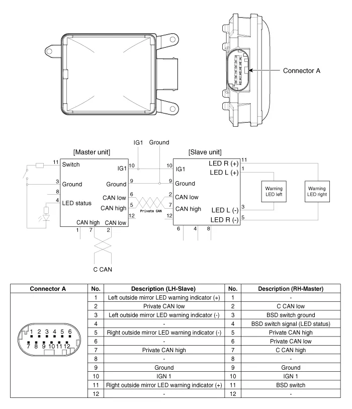
Kia Cadenza YG: Blind Spot Detection System / Blind Spot Detection Unit Schematic Diagrams
| Circuit Diagram |
Diagnosis With GDS 1. BSD system defects can be quickly diagnosed with the GDS. GDS operates actuator quickly to monitor, input/output value and self diagnosis.
Removal 1. Disconnect the negative (-) battery terminal. 2. Remove the rear bumper. (Refer to Body - "Rear Bumper") 3. Remove the BSD unit (A) after loosening the mounting screws.
Other information:
Kia Cadenza YG 2016-2021 Service Manual: Description and Operation
System Overview RPAS (Rear Parking Assist System) is an electronic driving aid that warns the driver to be cautious while parking or in low speed environments. The sensor uses ultrasonic waves to detect objects within proximity of the vehicle.
Kia Cadenza YG 2016-2021 Service Manual: Description and Operation
Description System Operation Typically, lane departure warning is activated at a speed over 70 KPH, but suppressed in case of unintentional lane departure when driver do not operate turn signal. System Operation Conditions 1. User Conditions (1) When unintended lane departure is occured, warnings are generated.
Categories
- Manuals Home
- Kia Cadenza Owners Manual
- Kia Cadenza Service Manual
- Body (Interior and Exterior)
- Engine Electrical System
- Emission Control System
- New on site
- Most important about car
