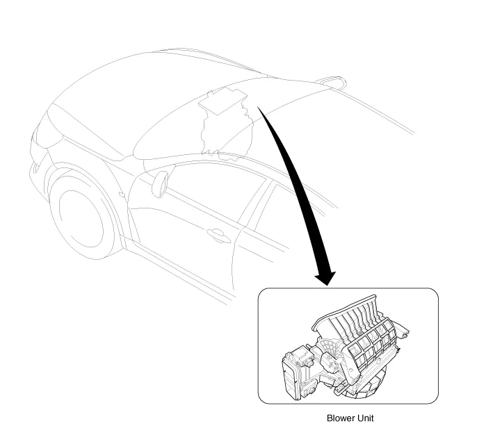
Kia Cadenza YG: Blower / Blower Unit Components and Components Location
| Component Location |
| Components |
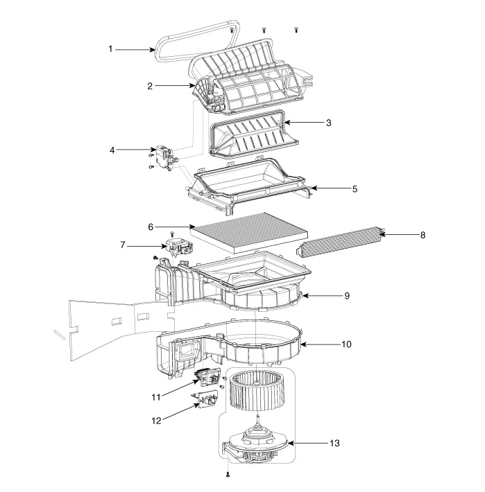
| 1. Duct Seal 2. Duct Case 3. Inlet Door 4. Intake Actuator 5. Inlet Duct Case (A) | 6. Climate control air filter 7. Cluster Ionizer 8. Climate control air filter Cover 9. Blower Upper Case 10. Blower Lower Case | 11. FET 12. Resistor 13. Blower Motor |
Replacement 1. Disconnect the negative (-) battery terminal. 2. Remove the heater and blower unit.(Refer to HA group – heater unit). 3. Remove the blower unit (A) from the heater unit after loosening a mounting bolt and 3 screws.
Other information:
Kia Cadenza YG 2016-2021 Service Manual: Adaptive Front Lighting System Description and Operation
Description AFLS Unit(ECU) AFLS located in Cockpit Module is provided information of vehicle (steering wheel signal,vehicle speed, inclination of vehicle). Based on provided information , it calculates algorithm and adjust Low beam of H/Lamp. It transmits driving information by using LIN protocol, it is operated in Fail-safe reaction mode
Kia Cadenza YG 2016-2021 Service Manual: Troubleshooting
Troubleshooting Examples of False-Alarm Occurrence from system characteristics (It’s not a problem) – Characteristics of EM Wave : EM Waves are reflected against all material and especially metal very well. Reflections of EM Waves are varies with the shape of object.
Categories
- Manuals Home
- Kia Cadenza Owners Manual
- Kia Cadenza Service Manual
- Transaxle Control Module (TCM) Repair procedures
- Brake System
- Body Electrical System
- New on site
- Most important about car
