Kia Cadenza YG: Evaporative Emission Control System / Canister Repair procedures
Kia Cadenza YG 2016-2021 Service Manual / Emission Control System / Evaporative Emission Control System / Canister Repair procedures
| Removal |
| 1. |
Turn the ignition switch OFF and disconnect the negative (-) battery cable. |
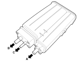
| 2. |
Disconnect the ventilation hose (A) from the fuel tank air filter. |
| 3. |
Disconnect the vapor tube quick-connector (B) and the quick-connector (C).
|

| 4. |
Remove installation bolts (A) and then remove the canister assembly.
|


| 5. |
Remove the bracket (A) from the canister after removing a bolts (B).
|


| Inspection |
| 1. |
Check for the following items visually.
A: Canister ↔ Atmosphere
B: Canister ↔ Fuel Tank
C: Canister ↔ Intake Manifold
|
| Installation |
| 1. |
Install in the reverse order of removal. |
Canister installation bolt :
3.9 ~ 5.9 N.m (0.4 ~ 0.6 kgf.m, 2.9 ~4.3 lb-ft) |
Schematic Diagram Canister Canister is filled with charcoal and absorbs evaporated vapor in fuel tank. The gathered fuel vapor in canister is drawn into the intake manifold by the ECM/PCM when appropriate conditions are set.
Operation Normal status Full fuelVehicle Rollover / steepValve openValve closeValve close
Other information:
Kia Cadenza YG 2016-2021 Service Manual: Blind Spot Detection Variant Coding Description and Operation
Description The used radar frequency of BSD is two, "North America region" and "Except North America region". If it replaces BSD unit, BSD unit has to perform the procedure of variant coding. BSD Variant Coding 1. Select the "BSD Variant Coding" procedure in BSD system.
Kia Cadenza YG 2016-2021 Service Manual: Special Service Tools
S
Categories
- Manuals Home
- Kia Cadenza Owners Manual
- Kia Cadenza Service Manual
- Transaxle Control Module (TCM) Repair procedures
- Automatic Transaxle System
- Body Electrical System
- New on site
- Most important about car

Copyright © 2026 www.kcadenzavg.com - 0.0214