Kia Cadenza YG: Engine Control System / CVVT Oil Control Valve (OCV) Repair procedures
Kia Cadenza YG 2016-2021 Service Manual / Engine Control / Fuel System / Engine Control System / CVVT Oil Control Valve (OCV) Repair procedures
| Inspection |
| 1. |
Turn the ignition switch OFF. |
| 2. |
Disconnect the OCV connector. |
| 3. |
Measure resistance between the OCV terminals 1 and 2. |
| 4. |
Check that the resistance is within the specification.
|
| Removal |
| [CVVT Oil Control Valve (Intake)] |
| 1. |
Turn the ignition switch OFF and disconnect the battery negative (-) cable. |
| 2. |
Remove the intake manifold.
(Refer to Engine Mechanical System - “Intake Manifold”) |
| 3. |
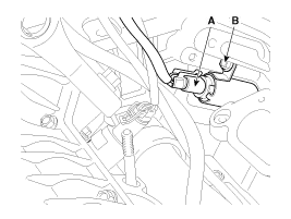
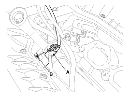
Disconnect the CVVT oil control valve connector (A). |
| 4. |
Remove the installation bolt (B), and then remove the valve from the engine.
[Bank 1]
[Bank 2]
|
| [CVVT Oil Control Valve (Bank1/Exhaust)] |
| 1. |
Turn the ignition switch OFF and disconnect the battery negative (-) cable. |
| 2. |
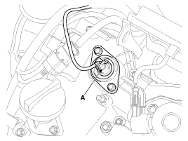
Disconnect the CVVT oil control valve connector (A).
|
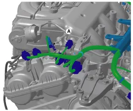
| 3. |
Remove the surge tank.
(Refer to Engine Mechanical System - "Surge Tank") |
| 4. |
Remove the cylinder head cover.
(Refer to Engine Mechanical System - “Cylinder Head Cover”) |
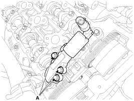
| 5. |
Remove the installation bolt (A), and then remove the valve from the engine.
|
| [CVVT Oil Control Valve (Bank2/Exhaust)] |
| 1. |
Turn the ignition switch OFF and disconnect the battery negative (-) cable. |
| 2. |
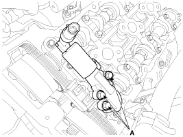
Disconnect the CVVT oil control valve connector (A).
|
| 3. |
Remove the cylinder head cover.
(Refer to Engine Mechanical System - “Cylinder Head Cover”) |
| 4. |
Remove the installation bolt (A), and then remove the valve from the engine.
|
| Inatallation |
|

|
|
| Items | Component Side | Harness Side |
| Bank 1 (RH) | Grey | |
| Bank 2 (LH) | Black | |
| 1. |
Install in the reverse order of removal.
|
Circuit Diagram
Description Variable Intake manifold Solenoid (VIS) valves are installed on the intake manifold (VIS Valve 1) and the surge tank (VIS Valve 2). These VIS valve 1 and 2 control vacuum modulators which activate valves in the intake manifold and the surge tank.
Other information:
Kia Cadenza YG 2016-2021 Service Manual: Description and Operation
Description Surround View Monitoring System (SVM) is the system that allows video monitoring of 360 degrees around the vehicle. The system includes 4 ultra optical camera mounted around the vehicle (front, both sides, rear). The video from these cameras are applied with distortion compensation, time point conversion, and video merging
Kia Cadenza YG 2016-2021 Service Manual: Specifications
S
Categories
- Manuals Home
- Kia Cadenza Owners Manual
- Kia Cadenza Service Manual
- Rail Pressure Sensor (RPS) Schematic Diagrams
- Battery Troubleshooting
- Alternator Schematic Diagrams
- New on site
- Most important about car

Copyright © 2026 www.kcadenzavg.com - 0.0203