Kia Cadenza YG: Lighting System / Door Lamp Repair procedures
Kia Cadenza YG 2016-2021 Service Manual / Body Electrical System / Lighting System / Door Lamp Repair procedures
| Removal |
| Mood Lamp |
| 1. |
Disconnect the negative (-) battery terminal. |
| 2. |
Remove the front door trim.
(Refer to Body - "Front Door") |
| 3. |
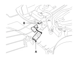
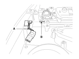
Remove the connector and LED mood lamp (A).
|

| 4. |
Remove the rear door trim.
(Refer to Body - "Rear Door") |
| 5. |
Remove the connector and LED mood lamp (A).
|
| Door Lamp |
| 1. |
Disconnect the negative (-) battery terminal. |
| 2. |
Remove the front door trim.
(Refer to Body - "Front Door") |
| 3. |
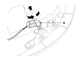
Turn the socket counterclockwise to remove the door lamp bulb (A).
|
| Installation |
| Mood Lamp |
| 1. |
Install the door mood lamp after connecting the connector. |
| 2. |
Install the door trim. |
| 3. |
Connect the negative (-) battery terminal. |
| Door Lamp |
| 1. |
Install the door lamp after connecting the connector. |
| 2. |
Install the door trim. |
| 3. |
Connect the negative (-) battery terminal. |
Rear Combination Lamp (Outside) 1. Disconnect the negative (-) battery terminal. 2. If the bulbs should be only replaced without removing lamp assembly, replace the turn signal lamp bulb (B) after removing the trim cover (A) in the trunk.
Removal 1. Disconnect the negative (-) battery terminal. 2. Remove the luggage room lamp (B) when prying the hole (A) with a flat-up screwdriver.
Other information:
Kia Cadenza YG 2016-2021 Service Manual: Components and Components Location
C
Kia Cadenza YG 2016-2021 Service Manual: Lane Departure Warning System (LDWS) Unit Repair procedures
Removal 1. Disconnect the negative (-) battery terminal. 2. Remove the LDWS unit cover (A). 3. Remove the LDWS unit connector (A). 4. Remove the LDWS unit after widening the mounting clips. Installation 1. Install the LDWS unit. 2.
Categories
- Manuals Home
- Kia Cadenza Owners Manual
- Kia Cadenza Service Manual
- Suspension System
- Engine Electrical System
- Brake System
- New on site
- Most important about car

Copyright © 2026 www.kcadenzavg.com - 0.0221