Kia Cadenza YG: Engine Control System / Heated Oxygen Sensor (HO2S) Repair procedures
| Inspection |
| 1. |
Turn the ignition switch OFF. |
| 2. |
Disconnect the HO2S connector. |
| 3. |
Measure resistance between the HO2S terminals 3 and 4. |
| 4. |
Check that the resistance is within the specification.
|
| Removal |
| 1. |
Turn the ignition switch OFF and disconnect the battery negative (-) cable. |
| 2. |
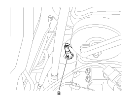
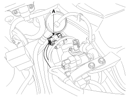
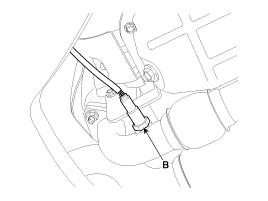
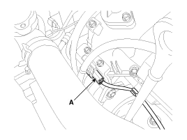
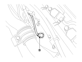
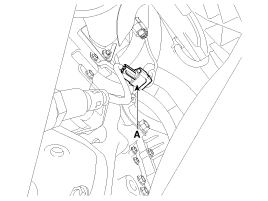
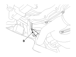
Disconnect the connector (A), and then remove the sensor (B).
[Bank 1/Sensor 1]
[Bank 1/Sensor 2]
[Bank 2/Sensor 1]
[Bank 2/Sensor 2]
|


| Installation |
|

|
| 1. |
Install in the reverse order of removal.
|
Circuit Diagram
Description Rail Pressure Sensor (RPS) is installed on the delivery pipe and measures the instantaneous fuel pressure in the delivery pipe. The sensing element (Semiconductor element) built in the sensor converts the pressure to voltage signal.
Other information:
Kia Cadenza YG 2016-2021 Service Manual: Adaptive Front Lighting System Repair procedures
Removal 1. Disconnect the negative (-) battery terminal. 2. Using a screwdriver or remover, remove the crash pad side cover (A). [RH] 3. Disconnect the stopper (B) from the glove box (A). 4. Disconnect the air damper (A) from the glove box (B).
Kia Cadenza YG 2016-2021 Service Manual: Description and Operation
Description BSD is a system that uses two magnetic wave radar sensors attached on the rear bumper to measure the distance from the following vehicles and provides the sensing and (visual and auditory) alarm of any vehicle coming into the blind spot.
Categories
- Manuals Home
- Kia Cadenza Owners Manual
- Kia Cadenza Service Manual
- Emission Control System
- Battery Troubleshooting
- Suspension System
- New on site
- Most important about car
