Kia Cadenza YG: Fuel Delivery System / High Pressure Fuel Pump Repair procedures

Removal
   
In case of removing the high pressure fuel pump, high pressure fuel pipe, delivery pipe, and injector, there may be injury caused by leakage of the high pressure fuel. So don’t do any repair work right after engine stops.
1.
Turn the ignition switch OFF and disconnect the battery negative (-) cable.
2.
Release the residual pressure in fuel line.
(Refer to the Fuel Delivery System - Repair Procedures - "Release Residual Pressure in Fuel Line").
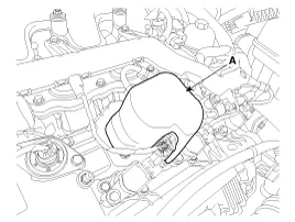
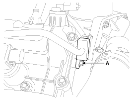
   
When removing the fuel pump fuse, a Diagnostic Trouble Code (DTC) may occur.
Delete the code with the GDS after completion of “Release Residual Pressure in Fuel Line” work.
3.
Remove the pump foam (A).
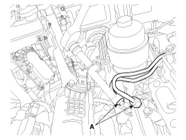
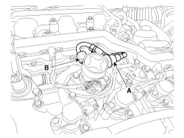
4.
Disconnect the fuel pressure control valve connector (A) and the fuel feed tube quick-connector (B).

5.
Remove the intake manifold.
(Refer to Engine Mechanical System - "Intake Manifold")
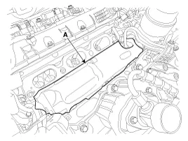
6.
Remove the injector foam (A).
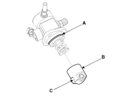
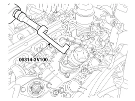
7.
Remove the high pressure fuel pipe.
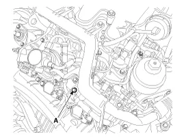
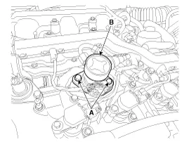
(1)
Remove the high pressure pipe flange nut in order of A,B with the special service tool [SST No.: 09314-3V100]

(2)
Remove the high pressure pipe bracket bolt (A).

(3)
Remove the function bolck installation bolt (A).

8.
Remove the installation bolts (A), and then remove the high pressure fuel pump (B) from the cylinder head assembly.
   
Unscrew in turn the two bolts in small step (0.5 turns). In case of fully unscrewing one of the two bolts with the other bolt installed, the housing surface of the cylinder head may be broken because of tension of the pump spring.

Installation
   
Be sure to check the low pressure fuel hose quick-connector (A) is completely connected to the high pressure fuel pump until a confirmation ''click'' sound is heard.
Be sure to re-check the low pressure fuel hose is completely connected to the high pressure fuel pump by pulling it after connecting.
Be sure to install the high pressure fuel pipe (B) with the specified torques.
Because fuel leak may cause fire, securely Inspect leakage of all fuel line connection parts at engine start condition.

   
Before installing the high pressure fuel pump, position the roller tappet in the lowest position by rotating the crankshaft. Otherwise the installation bolts may be broken because of tension of the pump spring.
   
Do not reuse the used bolt.
   
Do not reuse the used high pressure fuel pipe.
   
When tightening the installation bolts of the high pressure fuel pump, tighten in turn the bolts in small step (0.5 turns) after tightening them with hand-screwed torque.
   
Install the component with the specified torques.
First hand-tighten the fasteners fully until they are not fastened any more in order to have them inserted in place and then completely tighten to the specified torque using a torque wrench.
If not tightening the bolts or nuts in a straight line with the mating bolt holes or fittings, it may cause a fuel leak due to broken threads.
   
Note that internal damage may occur when the component is dropped. In this case, use it after inspecting.
   
Apply engine oil to the O-ring (A) of the high pressure fuel pump, the roller tappet (B), and the protrusion (C). Also apply engine oil to the groove on the location where the protrusion (C) is installed.

1.
Install in the reverse order of removal.
   
Use the special service tool [SST No.: 09314-3V100] to install the high pressure fuel pipe.


High pressure fuel pump installation bolt:
12.8 ~ 14.7 N.m (1.3 ~ 1.5 kgf.m, 9.4 ~ 10.9 lb-ft)
High pressure fuel pipe installation nut:
29.4 ~ 35.3 N.m (3.0 ~ 3.6 kgf.m, 21.7 ~ 26.0 lb-ft)
High pressure fuel pipe function block installation bolt:
7.8 ~ 11.8 N.m (0.8 ~ 1.2 kgf.m, 5.8 ~ 8.7 lb-ft)
High pressure fuel pipe bracket installation bolt:
7.8 ~ 11.8 N.m (0.8 ~ 1.2 kgf.m, 5.8 ~ 8.7 lb-ft)

    Removal     In case of removing the high pressure fuel pump, high pressure fuel pipe, delivery pipe, and injector, there may be injury caused by leakage of the high pressure fuel.

    Removal 1. Lift the vehicle and support the fuel tank with a jack. 2. Remove the nuts from fuel tank. 3. Release the fuel tank bands (A). 4.

    Other information:

    Kia Cadenza YG 2016-2021 Service Manual: Description and Operation

    Description BSD is a system that uses two magnetic wave radar sensors attached on the rear bumper to measure the distance from the following vehicles and provides the sensing and (visual and auditory) alarm of any vehicle coming into the blind spot.

    Kia Cadenza YG 2016-2021 Service Manual: Blower Motor Repair procedures

    Inspection 1. Connect the battery voltage and check the blower motor rotation. 2. If the blower motor voltage is not operated well, substitute with a known-good blower motor and check for proper operation. 3. If the problem is corrected, replace the blower motor.

    Categories

     
    Copyright © 2026 www.kcadenzavg.com - 0.0228