Kia Cadenza YG: IMS (Integrated Memory) / IMS Power Seat Control Repair procedures
Kia Cadenza YG 2016-2021 Service Manual / Body Electrical System / IMS (Integrated Memory) / IMS Power Seat Control Repair procedures
| Inspection |
| 1. |
Remove the IMS control switch connector (A).
|

| 2. |
With the IMS control switch in each position, make sure that
continuity exists between the terminals below. If continuity is not as
specified, replace the IMS control switch.
Driver Power Seat Control Switch (For IMS)
|

| Removal |
| 1. |
Disconnect the negative (-) battery terminal. |
| 2. |
Remove the switch (A) from seat side cover.
|

| 3. |
Remove the seat side cover (A).
(Refer to Body - "Front Seat")
|

| 4. |
Disconnect the IMS control switch connector (A).
|

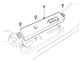
| 5. |
Loosen the IMS control switch (A) mounting screws (3EA).
|
| Installation |
|

| 1. |
Connect the connectors and reassemble the IMS control switch. |
| 2. |
Reassemble the seat side cover. |
Circuit diagram
Other information:
Kia Cadenza YG 2016-2021 Service Manual: Immobilizer Control Unit Repair procedures
Removal 1. Disconnect the negative (-) battery terminal. 2. Remove the crash pad lower panel. (Refer to Body - "Crash Pad") 3. Disconnect the 5P connector of the SMARTRA unit and then remove the SMARTRA unit (A) after loosening the bolt. Installation 1.
Kia Cadenza YG 2016-2021 Service Manual: Troubleshooting
Troubleshooting Problem Symptoms Table Before replacing or repairing air conditioning components, first determine if the malfunction is due to the refrigerant charge, air flow or compressor. Use the table below to help you find the cause of the problem.
Categories
- Manuals Home
- Kia Cadenza Owners Manual
- Kia Cadenza Service Manual
- Suspension System
- Transaxle Control Module (TCM) Repair procedures
- Body Electrical System
- New on site
- Most important about car

Copyright © 2026 www.kcadenzavg.com - 0.0276