Kia Cadenza YG: IMS (Integrated Memory) / IMS Power Seat Control Schematic Diagrams
| Circuit diagram |
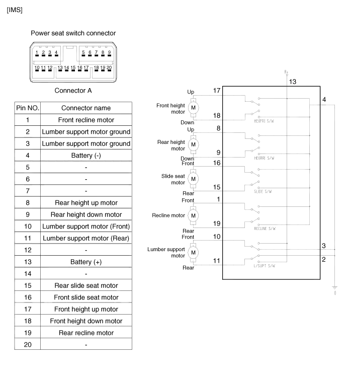
Inspection 1. Disconnect the IMS control switch connector. 2. With the power IMS control switch in each position, make sure that continuity exists between the terminals below.
Inspection 1. Remove the IMS control switch connector (A). 2. With the IMS control switch in each position, make sure that continuity exists between the terminals below.
Other information:
Kia Cadenza YG 2016-2021 Service Manual: Antenna Coil Repair procedures
Removal 1. Disconnect the negative (-) battery terminal. 2. Remove the crash pad lower panel. (Refer to Body - "Crash Pad") 3. Disconnect the 6P connector (B) of the coil antenna and then remove the coil antenna (A) after loosening the screw.
Kia Cadenza YG 2016-2021 Service Manual: Auto defoging actuator Repair procedures
Inspection 1. Ignition "OFF”. 2. Disconnect the connector of auto defog control actuator. 3. Verify that the auto defog control actuator operates to the defrost ON mode when connecting 12V to the terminal 3 and grounding terminal 7. 4.
Categories
- Manuals Home
- Kia Cadenza Owners Manual
- Kia Cadenza Service Manual
- Alternator Schematic Diagrams
- Rail Pressure Sensor (RPS) Schematic Diagrams
- Automatic Transaxle System
- New on site
- Most important about car
