Kia Cadenza YG: IMS (Integrated Memory) / IMS Control Switch Repair procedures
Kia Cadenza YG 2016-2021 Service Manual / Body Electrical System / IMS (Integrated Memory) / IMS Control Switch Repair procedures
| Inspection |
| 1. |
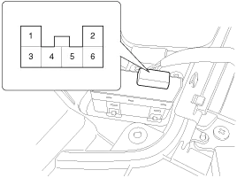
Disconnect the IMS control switch connector.
|
| 2. |
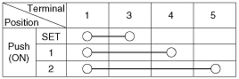
With the power IMS control switch in each position, make sure
that continuity exists between the terminals below. If continuity is
not as specified, replace the IMS control switch.
|
| Removal |
| 1. |
Disconnect the negative (-) battery terminal. |
| 2. |
Remove the front door trim panel.
(Refer to Body - "Front Door") |
| 3. |
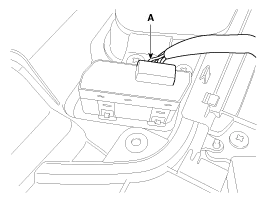
Remove the IMS switch connector (A) from door trim panel.
|
| 4. |
Remove the IMS control switch. |
| Installation |
|

| 1. |
Connect the connectors and reassemble the IMS control switch. |
| 2. |
Reassemble the front door trim panel. |
Circuit diagram
Circuit diagram
Other information:
Kia Cadenza YG 2016-2021 Service Manual: Blower Unit Components and Components Location
Component Location Components 1. Duct Seal2. Duct Case3. Inlet Door4. Intake Actuator5. Inlet Duct Case (A)6. Climate control air filter7. Cluster Ionizer8. Climate control air filter Cover9. Blower Upper Case10. Blower Lower Case11. FET12. Resistor13.
Kia Cadenza YG 2016-2021 Service Manual: Blower Motor Repair procedures
Inspection 1. Connect the battery voltage and check the blower motor rotation. 2. If the blower motor voltage is not operated well, substitute with a known-good blower motor and check for proper operation. 3. If the problem is corrected, replace the blower motor.
Categories
- Manuals Home
- Kia Cadenza Owners Manual
- Kia Cadenza Service Manual
- Suspension System
- Timing Chain Repair procedures
- Engine Mechanical System
- New on site
- Most important about car

Copyright © 2026 www.kcadenzavg.com - 0.024