
Kia Cadenza YG: Engine Control System / Manifold Absolute Pressure Sensor (MAPS) Schematic Diagrams
| Circuit Diagram |
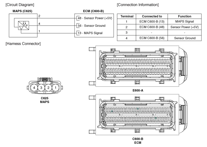
Specification Pressure [kPa (kgf/cm², psi)]Output Voltage (V)20.0 (0.20, 2.90)0.7946.66 (0.47, 6.77)1.84101.32 (1.03, 14.7)4.0
Inspection 1. Connect the GDS on the Data Link Connector (DLC). 2. Measure the output voltage of the MAPS at idle and IG ON. ConditionOutput Voltage (V)IG ONApprox.
Other information:
Kia Cadenza YG 2016-2021 Service Manual: Compressor Oil Repair procedures
Oil Specification 1. The HFC-134a system requires synthetic (PAG) compressor oil whereas the R-12 system requires mineral compressor oil. The two oils must never be mixed. 2. Compressor (PAG) oil varies according to compressor model. Be sure to use oil specified for the model of compressor.
Kia Cadenza YG 2016-2021 Service Manual: Evaporator unit Repair procedures
Inspection 1. Ignition "OFF". 2. Disconnect evaporator temperature sensor. 3. Using the multi-tester, Measure resistance between terminal "1" and "2" of evaporator temperature sensor. Specification Evaporator coretemperature [°C(°F)]Resistance[KΩ]Voltage[V]-20(-4)70.
Categories
- Manuals Home
- Kia Cadenza Owners Manual
- Kia Cadenza Service Manual
- Suspension System
- Crankshaft Damper Pulley Components and Components Location
- Components and Components Location
- New on site
- Most important about car
