Kia Cadenza YG: Audio / Multimedia jack Description and Operation
Kia Cadenza YG 2016-2021 Service Manual / Body Electrical System / Audio / Multimedia jack Description and Operation
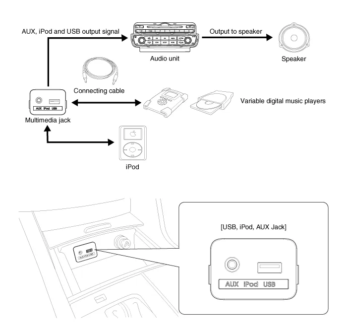
| Description |
The multimedia jack on the console upper cover is for
customers who like to listen to external portable music players like the
MP3, iPod and etc., through the vehicle''s sound system when it is
linked to this jack. The customer has this added option.
In case of distortions from media connected to the AUX
source, the audio unit may not be defective but the output level of the
used media does not match the specification of the AUX input.
Circuit Diagram
Removal 1. Remove the shift lever knob. (Refer to Body - "Console") 2. Remove the floor console upper cover. 3. Disconnect the connector (A) from the floor console upper cover.
Other information:
Kia Cadenza YG 2016-2021 Service Manual: Schematic Diagrams
C
Kia Cadenza YG 2016-2021 Service Manual: Auto defoging actuator Repair procedures
Inspection 1. Ignition "OFF”. 2. Disconnect the connector of auto defog control actuator. 3. Verify that the auto defog control actuator operates to the defrost ON mode when connecting 12V to the terminal 3 and grounding terminal 7. 4.
Categories
- Manuals Home
- Kia Cadenza Owners Manual
- Kia Cadenza Service Manual
- Body Electrical System
- Engine Mechanical System
- Timing Chain Repair procedures
- New on site
- Most important about car

Copyright © 2026 www.kcadenzavg.com - 0.0312