Kia Cadenza YG: Power Door Locks / Power Door Lock Switch Repair procedures
Kia Cadenza YG 2016-2021 Service Manual / Body Electrical System / Power Door Locks / Power Door Lock Switch Repair procedures
| Inspection |
Diagnosis With GDS
| 1. |
It will be able to diagnose defects of DDM/ADM with GDS
quickly. GDS can operates actuator forcefully, input/output value
monitoring and self diagnosis. |
| 2. |
Select model and "IPM". |
| 3. |
Select the "DDM (Power window main)" to check. |
| 4. |
Select "Input/output monitoring", if you will check current
data of power door lock system. It provides input/output status of
DDM/ADM.
|

| 5. |
If you will check the power door lock operation forcefully, select "Actuation test".
|

| 6. |
To check the DTC of the DDM/AMD module, select "Diagnostic trouble codes"
|

| Removal |
| 1. |
Disconnect the negative(-) battery terminal. |
| 2. |
Remove the front door trim panel.
(Refer to Body - "Front Door") |
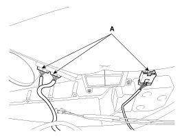
| 3. |
Disconnect the power window switch module connector (A) from the wiring harness.
|
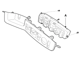
| 4. |
Remove the power window switch module (A) from the door trim after loosening the mounting screws (13EA).
|

| 5. |
Remove the module (A) from the sub box assembly after loosening the mounting screw (3EA).
|

| Installation |
| 1. |
Install the power window switch module. |
| 2. |
Install the door trim panel after reconnecting the relevant connectors
|
Inspection Front Door Lock Actuator Inspection 1. Remove the front door trim. (Refer to Body - "Front Door") 2. Remove the front door module.
Other information:
Kia Cadenza YG 2016-2021 Service Manual: Components and Components Location
C
Kia Cadenza YG 2016-2021 Service Manual: Blind Spot Detection Unit Repair procedures
Removal 1. Disconnect the negative (-) battery terminal. 2. Remove the rear bumper. (Refer to Body - "Rear Bumper") 3. Remove the BSD unit (A) after loosening the mounting screws. Take care not to separate the bracket from rear bumper when removing the BSD sensor.
Categories
- Manuals Home
- Kia Cadenza Owners Manual
- Kia Cadenza Service Manual
- Timing Chain Repair procedures
- Battery Troubleshooting
- Engine Electrical System
- New on site
- Most important about car

Copyright © 2026 www.kcadenzavg.com - 0.0282