Kia Cadenza YG: Power Door Locks / Power Door Lock Actuators Repair procedures
| Inspection |
| 1. |
Remove the front door trim.
(Refer to Body - "Front Door") |
| 2. |
Remove the front door module. |
| 3. |
Disconnect the 6P connector from the actuator.
|

| 4. |
Check actuator operation by connecting power and ground
according to the table. To prevent damage to the actuator, apply battery
voltage only momentarily.
|

| 1. |
Remove the rear door trim.
(Refer to Body - "Rear Door") |
| 2. |
Remove the rear door module. |
| 3. |
Disconnect the 6P connector from the actuator.
|
| 4. |
Check actuator operation by connecting power and ground
according to the table. To prevent damage to the actuator, apply battery
voltage only momentarily.
|

| 1. |
Remove the trunk lid trim panel.
(Refer to Body - "Trunk Lid") |
| 2. |
Disconnect the 3P connector from the actuator.
|
| 3. |
Check actuator operation by connecting power and ground
according to the table. To prevent damage to the actuator, apply battery
voltage only momentarily.
|

| 1. |
Remove the front door trim panel.
(Refer to Body - "Front Door") |
| 2. |
Remove the front door module. |
| 3. |
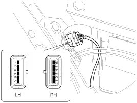
Disconnect the 6P connector from the actuator.
|
| 4. |
Check for continuity between the terminals in each switch position when inserting the key into the door according to the table.
|

| 1. |
Remove the rear door trim panel.
(Refer to Body - "Rear Door") |
| 2. |
Remove the rear door module. |
| 3. |
Disconnect the 6P connector from the actuator.
|
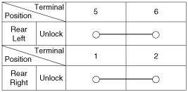
| 4. |
Check for continuity between the terminals in each switch position according to the table.
|
| 1. |
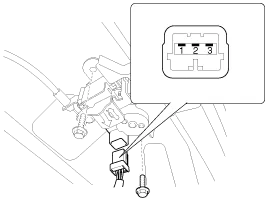
Remove the trunk lid trim.
(Refer to Body - "Trunk Lid") |
| 2. |
Disconnect the 3P connector from the actuator.
|
| 3. |
Check for continuity between the terminals in each switch position according to the table.
|

Component Location 1. Driver power window switch2. Door lock switch3. IPM(Intelligent intergrated Platform Module)4. Front door lock actuator5. Rear door lock actuator6.
Inspection Diagnosis With GDS 1. It will be able to diagnose defects of DDM/ADM with GDS quickly. GDS can operates actuator forcefully, input/output value monitoring and self diagnosis.
Other information:
Kia Cadenza YG 2016-2021 Service Manual: Description and Operation
Description System Overview The System offers the following features: – Human / machine interface through a 1-stage button, for terminal switching and engine start. – Control of external relays for ACC / IGN1 / IGN2 terminal switching and STARTER, without use of mechanical ignition switch.
Kia Cadenza YG 2016-2021 Service Manual: Power Mosfet Repair procedures
Inspection 1. Ignition "ON" 2. Manually operate the control switch and measure the voltage of blower motor. 3. Select the control switch to raise voltage until high speed. Specification FanMotor VoltageManualFirst speed3.8 ±0.5VSecond speed5.
Categories
- Manuals Home
- Kia Cadenza Owners Manual
- Kia Cadenza Service Manual
- General Information
- Transaxle Control Module (TCM) Repair procedures
- Timing Chain Repair procedures
- New on site
- Most important about car
