Kia Cadenza YG: Seat Electrical / Power Seat Motor Repair procedures
Kia Cadenza YG 2016-2021 Service Manual / Body Electrical System / Seat Electrical / Power Seat Motor Repair procedures
| Inspection |
Power Seat Motor
| 1. |
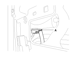
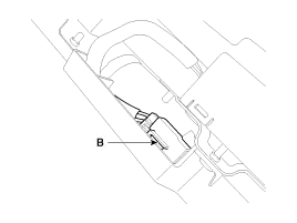
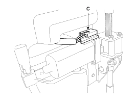
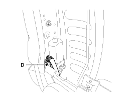
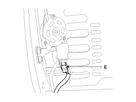
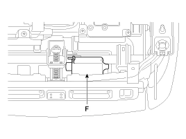
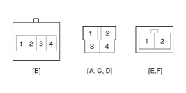
Disconnect the connectors for each motor.
A : Front height motor
B : Slide motor
C : Rear height motor
D : Recline motor
E : Lumber support motor
F : Cushion extension motor
|
| 2. |
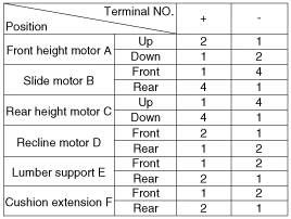
With the battery connected directly to the motor terminals, check if the motors run smoothly. |
| 3. |
Reverse the connections and check that the motor turns in reverse. |
| 4. |
If there is an abnormality, replace the motors.
|
Component Location 1. Slide motor2. Front height motor3. Rear height motor4. Lumber support motor5. Power seat control switch6. Recline motor7. Recline control switch8.
Circuit Diagram
Other information:
Kia Cadenza YG 2016-2021 Service Manual: Immobilizer Control Unit Repair procedures
Removal 1. Disconnect the negative (-) battery terminal. 2. Remove the crash pad lower panel. (Refer to Body - "Crash Pad") 3. Disconnect the 5P connector of the SMARTRA unit and then remove the SMARTRA unit (A) after loosening the bolt. Installation 1.
Kia Cadenza YG 2016-2021 Service Manual: Antenna Coil Repair procedures
Removal 1. Disconnect the negative (-) battery terminal. 2. Remove the crash pad lower panel. (Refer to Body - "Crash Pad") 3. Disconnect the 6P connector (B) of the coil antenna and then remove the coil antenna (A) after loosening the screw.
Categories
- Manuals Home
- Kia Cadenza Owners Manual
- Kia Cadenza Service Manual
- Battery Troubleshooting
- General Information
- Engine Control / Fuel System
- New on site
- Most important about car

Copyright © 2026 www.kcadenzavg.com - 0.0211