Kia Cadenza YG: Seat Electrical / Power Seat Control Switch Schematic Diagrams
Kia Cadenza YG 2016-2021 Service Manual / Body Electrical System / Seat Electrical / Power Seat Control Switch Schematic Diagrams
| Circuit Diagram |
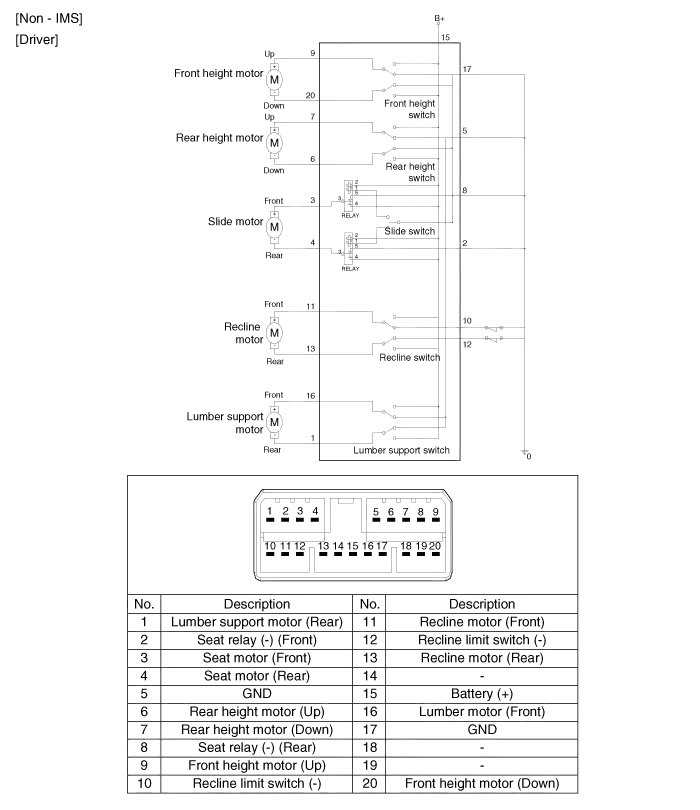
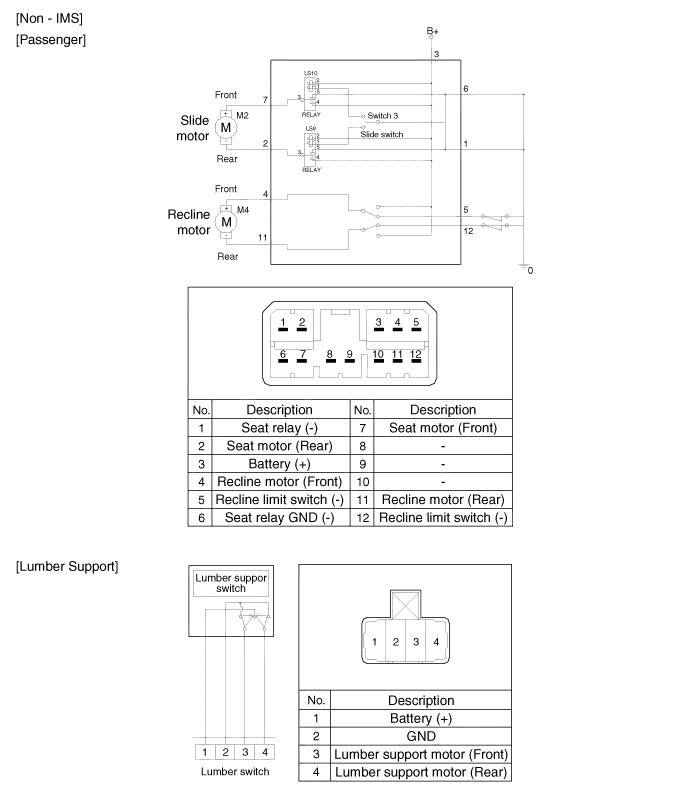
Inspection Power Seat Motor 1. Disconnect the connectors for each motor. A : Front height motor B : Slide motor C : Rear height motor D : Recline motor E : Lumber support motor F : Cushion extension motor 2.
Inspection With the power seat switch in each position, make sure that continuity exists between the terminals below. If continuity is not as specified, replace the power seat switch.
Other information:
Kia Cadenza YG 2016-2021 Service Manual: Troubleshooting
Troubleshooting Examples of False-Alarm Occurrence from system characteristics (It’s not a problem) – Characteristics of EM Wave : EM Waves are reflected against all material and especially metal very well. Reflections of EM Waves are varies with the shape of object.
Kia Cadenza YG 2016-2021 Service Manual: Temperature Control Actuator Description and Operation
D
Categories
- Manuals Home
- Kia Cadenza Owners Manual
- Kia Cadenza Service Manual
- Brake System
- Automatic Transaxle System
- General Information
- New on site
- Most important about car

Copyright © 2026 www.kcadenzavg.com - 0.0297