Kia Cadenza YG: Engine Control System / Purge Control Solenoid Valve (PCSV) Repair procedures
| Inspection |
| 1. |
Turn the ignition switch OFF. |
| 2. |
Disconnect the PCSV connector. |
| 3. |
Measure resistance between the PCSV terminals 1 and 2. |
| 4. |
Check that the resistance is within the specification.
|
| Removal |
| 1. |
Turn the ignition switch OFF and disconnect the battery negative (-) cable. |
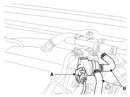
| 2. |
Disconnect the purge control solenoid valve connector (A). |
| 3. |
Disconnect the vapor hoses (B) from the purge control solenoid valve. |
| 4. |
Remove the valve from the bracket.
|
| Installation |
|

|
| 1. |
Install in the reverse order of removal.
|
Circuit Diagram
Description Continuous Variable Valve Timing (CVVT) system advances or retards the valve timing of the intake and exhaust valve in accordance with the ECM control signal which is calculated by the engine speed and load.
Other information:
Kia Cadenza YG 2016-2021 Service Manual: Auto defoging sensor Repair procedures
Inspection 1. Press the OFF switch more then 4 times within 2 seconds while pressing the MODE switch. DisplayFail description00Normal23Auto defog sensor OPEN24Auto defog sensor SHORT43Defog door potentiometer OPEN/SHORT44Defog door potentiometer * Diagnostic procedure refer to DTC code.
Kia Cadenza YG 2016-2021 Service Manual: Power Mosfet Repair procedures
Inspection 1. Ignition "ON" 2. Manually operate the control switch and measure the voltage of blower motor. 3. Select the control switch to raise voltage until high speed. Specification FanMotor VoltageManualFirst speed3.8 ±0.5VSecond speed5.
Categories
- Manuals Home
- Kia Cadenza Owners Manual
- Kia Cadenza Service Manual
- General Information
- Timing Chain Repair procedures
- Emission Control System
- New on site
- Most important about car
