Kia Cadenza YG: Engine Control System / Rail Pressure Sensor (RPS) Repair procedures
| Inspection |
| 1. |
Connect the GDS on the Data Link Connector (DLC). |
| 2. |
Measure the output voltage of the RPS at idle and various engine speed.
|
| Removal |
| 1. |
Turn the ignition switch OFF and disconnect the battery negative (-) cable. |
| 2. |
Release the residual pressure in fuel line.
(Refer to the Fuel Delivery System - Repair Procedures - "Release Residual Pressure in Fuel Line").
|

| 3. |
Remove the intake manifold.
(Refer to Engine Mechanical System - “Intake Manifold”) |
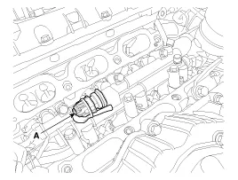
| 4. |
Disconnect the rail pressure sensor connector (A), and then remove the sensor from the delivery pipe.
|
| Installation |
|
| 1. |
Install in the reverse order of removal.
|
Circuit Diagram
Description Continuous Variable Valve Timing (CVVT) system advances or retards the valve timing of the intake and exhaust valve in accordance with the ECM control signal which is calculated by the engine speed and load.
Other information:
Kia Cadenza YG 2016-2021 Service Manual: Repair procedures
Removal 1. Remove the trunk trim in the trunk after removing the screws and clips. (Refer to Body - "Trunk") 2. Remove the camera holder (A) as shown arrow direction, and then remove the back view camera (B). Installation 1. Install the back view camera and camera holder.
Kia Cadenza YG 2016-2021 Service Manual: Blind Spot Detection Switch Repair procedures
Removal 1. Disconnect the negative (-) battery terminal. 2. Remove the passenger compartment junction box cover. 3. Remove the driver side cover (A). 4. Remove the crash pad side switch assembly (A) by pushing it through side cover hole.
Categories
- Manuals Home
- Kia Cadenza Owners Manual
- Kia Cadenza Service Manual
- Engine Control / Fuel System
- Suspension System
- Emission Control System
- New on site
- Most important about car
