Kia Cadenza YG: Rear Suspension System / Rear Cross Member Repair procedures
| Replacement |
| 1. |
Remove the rear wheel & tire.
|

| 2. |
Remove the rear lower arm.
(Refer to Rear Suspension System - "Rear Lower Arm") |
| 3. |
Remove the rear shock absorber.
(Refer to Rear Suspension System - "Rear Shock Absorber") |
| 4. |
Remove the rear upper arm.
(Refer to Rear Suspension System - "Rear Upper Arm") |
| 5. |
Remove the trailing arm.
(Refer to Rear Suspension System - "Trailing Arm") |
| 6. |
Remove the rear assist arm.
(Refer to Rear Suspension System - "Rear Assist Arm") |
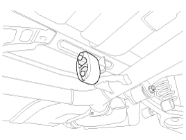
| 7. |
Remove the rear muffler.
|
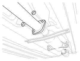

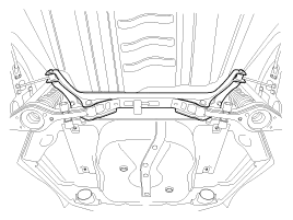
| 8. |
Loosen the mounting bolts and then remove the rear cross member with the frame.
|
| 9. |
Installation is the reverse of removal. |
Replacement 1. Remove the rear wheel & tire. Tightening torque: 88.3 ~ 107.9N.m (9.0 ~ 11.0kgf.m, 65.1 ~ 79.6lb-ft) Be careful not to damage to the hub bolts when removing the rear wheel & tire.
Other information:
Kia Cadenza YG 2016-2021 Service Manual: Description and Operation
Description Back view camera will activate when the backup light is ON with the ignition switch ON and the shift lever in the R position. This system is a supplemental system that shows behind the vehicle through the ECM (Reverse Display Room Mirror) mirror or AVN head unit while backing-up.
Kia Cadenza YG 2016-2021 Service Manual: Specifications
Specification Air Conditioner ItemSpecificationCompressorType6VSX16Oil type & CapacityPAG OIL 100±10Pulley type6PK-TYPEDisplacement160cc/revCondenserHeat rejection14,400 ±5% kcal/hrA/C Pressure transducerThe method to measure the pressureVoltage= 0.
Categories
- Manuals Home
- Kia Cadenza Owners Manual
- Kia Cadenza Service Manual
- Suspension System
- Engine Mechanical System
- General Information
- New on site
- Most important about car
