Kia Cadenza YG: Rear Glass Defogger / Rear Glass Defogger Switch Repair procedures
Kia Cadenza YG 2016-2021 Service Manual / Body Electrical System / Rear Glass Defogger / Rear Glass Defogger Switch Repair procedures
| Inspection |
| 1. |
The rear glass defogger switch inputs can be checked using the GDS. |
| 2. |
To check the input value of rear glass defogger switch, select option "IPM". |
| 3. |
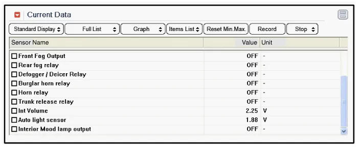
To consult the present input/output value of IPM, "Current
DATA". It provides information of IPM input/output conditions of rear
defogger relay.
|
| 4. |
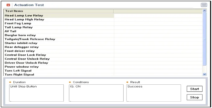
To check the input value of rear glass defogger switch in force mode, select option "Actuation Test".
|
| Removal |
| 1. |
Disconnect the negative (-) battery terminal. |
| 2. |
Remove the center fascia panel.
(Refer to Body - "Crash Pad") |
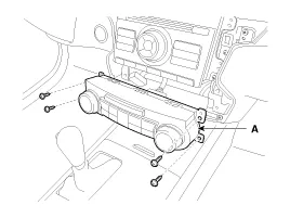
| 3. |
Remove the heater control unit (A) after removing screws (4EA).
|
| Installation |
| 1. |
Install the heater control unit. |
| 2. |
Install the center fascia panel. |
Inspection Wrap tin foil around the end of the voltmeter test lead to prevent damaging the heater line. Apply finger pressure on the tin foil, moving the tin foil along the grid line to check for open circuits.
Other information:
Kia Cadenza YG 2016-2021 Service Manual: Specifications
Specification Air Conditioner ItemSpecificationCompressorType6VSX16Oil type & CapacityPAG OIL 100±10Pulley type6PK-TYPEDisplacement160cc/revCondenserHeat rejection14,400 ±5% kcal/hrA/C Pressure transducerThe method to measure the pressureVoltage= 0.
Kia Cadenza YG 2016-2021 Service Manual: Heater Unit Components and Components Location
Component Location Components 1. Heater Case (LH)2. Separator3. Evaporator Core4. Shower Duct (LH)5. Heater Core Cover6. Heater Core7. Mode Actuator8. Mode Cam9. Temp Actuator (Drive)10. Vent Door Arm11. Floor Door Arm 1. Heater Case (RH)2.
Categories
- Manuals Home
- Kia Cadenza Owners Manual
- Kia Cadenza Service Manual
- Timing Chain Repair procedures
- Brake System
- Body (Interior and Exterior)
- New on site
- Most important about car

Copyright © 2026 www.kcadenzavg.com - 0.0196