Kia Cadenza YG: Smart key System / Smart key unit Schematic Diagrams
| Circuit Diagram |

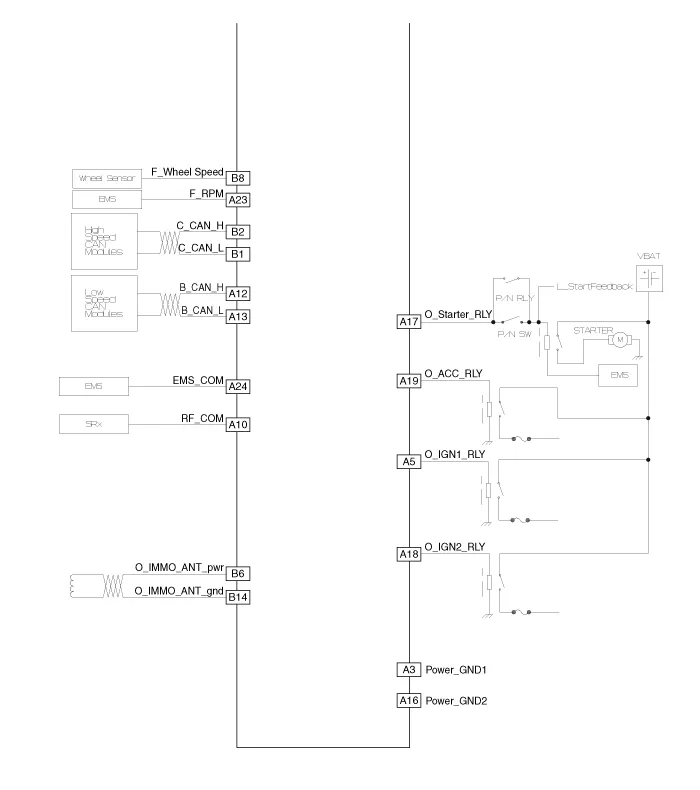
Component (1) Connector Pin Information No.Connector A (26 pins)Connector B (16 pins)Connector C (22 pins)1VBAT loadC CAN lowSSB illumination ground2-C CAN high-3Power ground 1-SSB LED OFF4IGN 1-Interior antenna #2 power5IGN1 relayBrake switchInterior antenna #1 power6ACCImmobilizer antenna power-7IGN 2--8SSB switch 2Wheel speedTrunk antenna power9-Driver toggle buttonBumper antenna power10RF COM-Assist side antena power11--Driver side antenna power12B CAN highP position/ Clutch switchSSB LED IGN13B CAN lowStart feedbackSSB illumination power14VBAT CPUImmobilizer antenna ground-15--Interior antenna #2 ground16Power ground 2SSB LED ACCInterior antenna #1 ground17Starter relay -18IGN2 relay-19ACC relayTrunk antenna ground20-Bumper antenna ground21-Assist side antena ground22-Driver side antenna ground23RPM 24EMS COM25SSB switch 126Assist toggle button Component (2)
Inspection Smart Key Unit – Refer to the BE group - inspection / self diagnosis with GDS. Smart Key Switch – Refer to the BE group - inspection / self diagnosis with GDS.
Other information:
Kia Cadenza YG 2016-2021 Service Manual: Description and Operation
Description Surround View Monitoring System (SVM) is the system that allows video monitoring of 360 degrees around the vehicle. The system includes 4 ultra optical camera mounted around the vehicle (front, both sides, rear). The video from these cameras are applied with distortion compensation, time point conversion, and video merging
Kia Cadenza YG 2016-2021 Service Manual: Intake Actuator Description and Operation
D
Categories
- Manuals Home
- Kia Cadenza Owners Manual
- Kia Cadenza Service Manual
- Timing Chain Repair procedures
- Battery Troubleshooting
- Body (Interior and Exterior)
- New on site
- Most important about car
