Kia Cadenza YG: Smart key System / Smart key unit Components and Components Location
Kia Cadenza YG 2016-2021 Service Manual / Body Electrical System / Smart key System / Smart key unit Components and Components Location
| Component (1) |
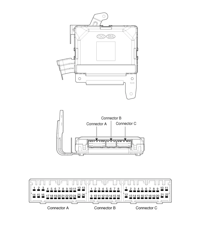
Connector Pin Information
| No. | Connector A (26 pins) | Connector B (16 pins) | Connector C (22 pins) |
| 1 | VBAT load | C CAN low | SSB illumination ground |
| 2 | - | C CAN high | - |
| 3 | Power ground 1 | - | SSB LED OFF |
| 4 | IGN 1 | - | Interior antenna #2 power |
| 5 | IGN1 relay | Brake switch | Interior antenna #1 power |
| 6 | ACC | Immobilizer antenna power | - |
| 7 | IGN 2 | - | - |
| 8 | SSB switch 2 | Wheel speed | Trunk antenna power |
| 9 | - | Driver toggle button | Bumper antenna power |
| 10 | RF COM | - | Assist side antena power |
| 11 | - | - | Driver side antenna power |
| 12 | B CAN high | P position/ Clutch switch | SSB LED IGN |
| 13 | B CAN low | Start feedback | SSB illumination power |
| 14 | VBAT CPU | Immobilizer antenna ground | - |
| 15 | - | - | Interior antenna #2 ground |
| 16 | Power ground 2 | SSB LED ACC | Interior antenna #1 ground |
| 17 | Starter relay | | - |
| 18 | IGN2 relay | - | |
| 19 | ACC relay | Trunk antenna ground | |
| 20 | - | Bumper antenna ground | |
| 21 | - | Assist side antena ground | |
| 22 | - | Driver side antenna ground | |
| 23 | RPM | | |
| 24 | EMS COM | ||
| 25 | SSB switch 1 | ||
| 26 | Assist toggle button |
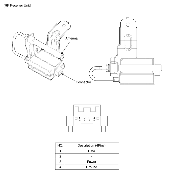
| Component (2) |
Smart Key Smart Key Code Saving 1. Connect the DLC cable of GDS to the data link connector in driver side crash pad lower panel, turn the power on GDS.
Circuit Diagram
Other information:
Kia Cadenza YG 2016-2021 Service Manual: Description and Operation
Description BSD is a system that uses two magnetic wave radar sensors attached on the rear bumper to measure the distance from the following vehicles and provides the sensing and (visual and auditory) alarm of any vehicle coming into the blind spot.
Kia Cadenza YG 2016-2021 Service Manual: Blind Spot Detection Switch Repair procedures
Removal 1. Disconnect the negative (-) battery terminal. 2. Remove the passenger compartment junction box cover. 3. Remove the driver side cover (A). 4. Remove the crash pad side switch assembly (A) by pushing it through side cover hole.
Categories
- Manuals Home
- Kia Cadenza Owners Manual
- Kia Cadenza Service Manual
- Engine Mechanical System
- Engine Electrical System
- Suspension System
- New on site
- Most important about car

Copyright © 2026 www.kcadenzavg.com - 0.0245