Kia Cadenza YG: Automatic Transaxle Control System / SS-B Solenoid Valve(ON/OFF) Repair procedures
Kia Cadenza YG 2016-2021 Service Manual / Automatic Transaxle System / Automatic Transaxle Control System / SS-B Solenoid Valve(ON/OFF) Repair procedures
| Inspection |
| 1. |
Turn ignition switch OFF. |
| 2. |
Remove the battery and battery tray.
(Refer to Engine Electrical System - "Battery") |
| 3. |
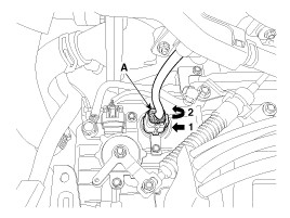
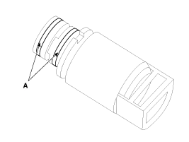
Disconnect the solenoid valve connector (A).
|
| 4. |
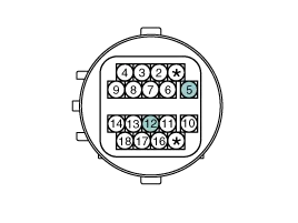
Measure the resistance between power terminal (5) and signal terminal (12).
|
| Removal |
| 1. |
Remove the under cover.
(Refer to Engine Mechanical System - "Engine Room Under Cover") |
| 2. |
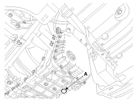
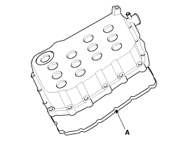
Remove the ATF drain plug (A), allow the fluid to drain out and then reinstall the drain plug.
|

| 3. |
Remove the battery and battery tray.
(Refer to Engine Electrical System - "Battery") |
| 4. |
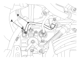
Remove the wiring bracket (A) and the air breather hose (B).
|
| 5. |
Lift the vehicle after loosening valve body cover upper bolts. |
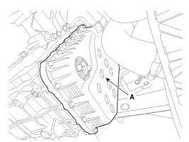
| 6. |
Remove the valve body cover (A) by loosening bolts.
|
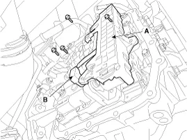
| 7. |
Remove the solenoid valve harness (A) and oil temperature sensor (B) after removing the bolts.
|
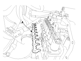
| 8. |
Remove solenoid valve support bracket (A).
|
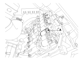
| 9. |
Remove the SS-B solenoid valve (A).
|
| Installation |
| 1. |
Install in the reverse order of removal.
|
Circuit Diagram
Description Inhibitor Switch monitors the lever''s position(P, R, N, D) and is used to control gear setting signals.
Other information:
Kia Cadenza YG 2016-2021 Service Manual: Components and Components Location
Component Location 1. Start Stop Button(SSB)2. FOB key3. RF receiver4. Smart key unit5. Interior antenna 16. Interior antenna 2 7. Trunk antenna8. Bumper antenna9. Door handle & door antenna10. Trunk lid open switch11.
Kia Cadenza YG 2016-2021 Service Manual: Compressor Oil Repair procedures
Oil Specification 1. The HFC-134a system requires synthetic (PAG) compressor oil whereas the R-12 system requires mineral compressor oil. The two oils must never be mixed. 2. Compressor (PAG) oil varies according to compressor model. Be sure to use oil specified for the model of compressor.
Categories
- Manuals Home
- Kia Cadenza Owners Manual
- Kia Cadenza Service Manual
- Timing Chain Repair procedures
- Engine Control / Fuel System
- Emission Control System
- New on site
- Most important about car

Copyright © 2026 www.kcadenzavg.com - 0.0225