Kia Cadenza YG: Electric Power Steering / Steering Gear box Repair procedures
Kia Cadenza YG 2016-2021 Service Manual / Steering System / Electric Power Steering / Steering Gear box Repair procedures
| Replacement |
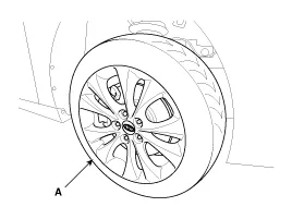
| 1. |
Remove the front wheel & tire (A).
|

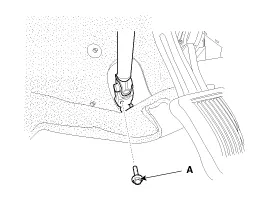
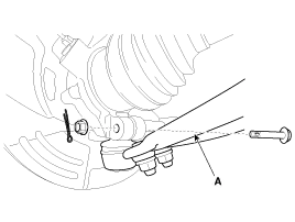
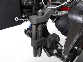
| 2. |
Loosen the bolt (A) and then disconnect the universal joint assembly from the pinion of the steering gear box.
|
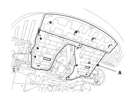
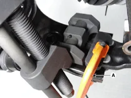
| 3. |
Remove the under cover (A).
|
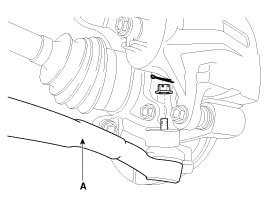
| 4. |
Remove the sprit pin and castle nut and then disconnect the tie-rod end (A) from the front knuckle.
|
| 5. |
Loosen the bolt & nut and then remove the lower arm (A).
|
| 6. |
Remove the front lower arm from the front knuckle using the SST (0K545-A9100).
|
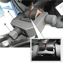

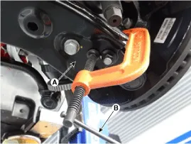
| 7. |
Disconnect the stabilizer link (B) with the front strut assembly (A) after loosening the nut.
|
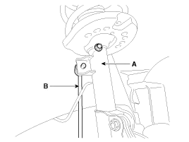
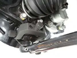
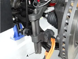
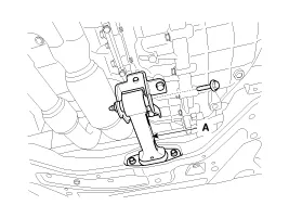
| 8. |
Loosen the bolt and then remove the front roll stopper (A).
|
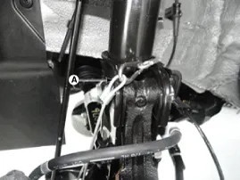
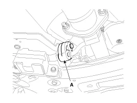
| 9. |
Disconnect the muffler rubber hanger (A).
|
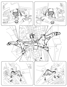
| 10. |
Loosen the bolts & nuts and then remove the sub frame (A).
|
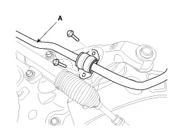
| 11. |
Remove the stabilizer bar (A).
|
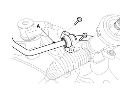
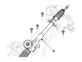
| 12. |
Remove steering gear box (A) from the front sub frame by loosening the mounting bolts.
|
| 13. |
Installation is the reverse of removal. |
| 14. |
Check the alignment.
(Refer to Suspension System - "Alingnent") |
Components 1. Tie-rod end2. Lock nut3. Bellows4. Bellows clip5. Tie rod6. Rack bar7. Dust packing8. Dust cap9. Oil seal10. Pinion plug11. Pinion assembly12.
Other information:
Kia Cadenza YG 2016-2021 Service Manual: Repair procedures
Inspection Initialization and diagnosis sequence by using diagnostic equipment Below content summarize the procedure for A/S using Diagnostic equipment Download Parameter 1. Select "AFLS" menu after selecting a vehicle. 2. Select "Parameter download" menu for define a characteristc of vehicle.
Kia Cadenza YG 2016-2021 Service Manual: Troubleshooting
Troubleshooting Problem Symptoms Table Before replacing or repairing air conditioning components, first determine if the malfunction is due to the refrigerant charge, air flow or compressor. Use the table below to help you find the cause of the problem.
Categories
- Manuals Home
- Kia Cadenza Owners Manual
- Kia Cadenza Service Manual
- Steering System
- Transaxle Control Module (TCM) Repair procedures
- Engine Control / Fuel System
- New on site
- Most important about car

Copyright © 2026 www.kcadenzavg.com - 0.0294