Kia Cadenza YG: MTS System / Telemetics Unit (TMU) Components and Components Location
| Component |
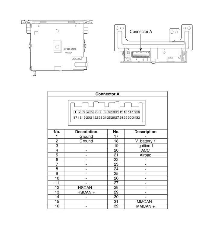
| No. | Pin Name | Type | From | To | Description (Wiring Spec.) |
| 1 | GND | DC Ground | TMU | Battery | Connected to battery ground |
| 2 | GND | DC Ground | TMU | Battery | Connected to battery ground |
| 3 | - | - | - | - | - |
| 4 | - | - | - | - | - |
| 5 | - | - | - | - | - |
| 6 | - | - | - | - | - |
| 7 | - | - | - | - | - |
| 8 | - | - | - | - | - |
| 9 | - | - | - | - | - |
| 10 | - | - | - | - | - |
| 11 | - | - | - | - | - |
| 12 | HS CAN (-) | Data I/O | BUS | BUS | High Speed CAN bus low |
| 13 | HS CAN (+) | Data I/O | BUS | BUS | High Speed CAN bus high |
| 14 | - | - | - | - | - |
| 15 | - | - | - | - | - |
| 16 | - | - | - | - | - |
| 17 | - | - | - | - | - |
| 18 | V battery 1 | DC Input | Battery | TMU | DC level input from battery Supply power to TMU |
| 19 | Ignition 1 | Data Input | Junction Box | TMU | Vehicle Key mode status |
| 20 | ACC | Data Input | Junction Box | TMU | Vehicle Key mode status |
| 21 | Airbag | Data Input | ACU | TMU | Airbag status data from ACU |
| 22 | - | - | - | - | - |
| 23 | - | - | - | - | - |
| 24 | - | - | - | - | - |
| 25 | - | - | - | - | - |
| 26 | - | - | - | - | - |
| 27 | - | - | - | - | - |
| 28 | - | - | - | - | - |
| 29 | - | - | - | - | - |
| 30 | - | - | - | - | - |
| 31 | MM CAN (-) | Data I/O | BUS | BUS | Low Speed CAN bus low |
| 32 | MM CAN (+) | Data I/O | BUS | BUS | Low Speed CAN bus high |
Description The Vehicle Information System is a Telematics service that ensures comfortable and enjoyable driving by providing safety, security, and vehicle diagnostic information, with the option of using your smartphone.
Removal • Take care not to scratch the crash pad and related parts. 1. Disconnect the negative (-) battery terminal.
Other information:
Kia Cadenza YG 2016-2021 Service Manual: Auto Head lamp leveling Unit Repair procedures
Removal Height Sensor 1. Remove the height sensor connector (A). 2. Loosen the mounting bolts(Body: 2EA, chassis: 1EA) from height sensor bracket. Tightening torque : 3 ~ 5N.m (30 ~ 50kgf.m, 2.21 ~ 3.68lb-ft) 3. Remove the height sensor.
Kia Cadenza YG 2016-2021 Service Manual: Compressor Oil Repair procedures
Oil Specification 1. The HFC-134a system requires synthetic (PAG) compressor oil whereas the R-12 system requires mineral compressor oil. The two oils must never be mixed. 2. Compressor (PAG) oil varies according to compressor model. Be sure to use oil specified for the model of compressor.
Categories
- Manuals Home
- Kia Cadenza Owners Manual
- Kia Cadenza Service Manual
- Transaxle Control Module (TCM) Repair procedures
- Suspension System
- Timing Chain Repair procedures
- New on site
- Most important about car
